3 minute read
3.7 Front power takeoff shaft


3.7 Front power takeoff shaft
The front power takeoff shaft is mounted on the tractor upon request. The FPTO is intended to drive agricultural machines with active working units, located on the front lift linkage. The front PTO has an independent drive with clockwise rotation of the PTO shaft end extension when looked at its end, and provides 1000 rpm of shaft end extension speed under 2100 rpm of the engine crankshaft speed with 44 kW of power implementation.
The front power take-off shaft is executed as an independent unit and is a planetary reduction unit with band brakes, mated with a parallel-shaft reduction gear unit. The torque to FPTO is transferred from a pulley 1 (figure 3.7.1) of the engine crankshaft to PTO reduction unit 9 through a spacer 2, secured on the crankshaft, an expansion clutch 3, installed in the spacer 2, and a splined shaft 4, secured in a clutch 5, which can be fixedly displaced in axial direction and which is mounted on the input shaft 8 of the PTO reduction unit. The power in the FPTO reduction unit 9 is transferred from the input shaft 8 to the end extension 12 by means of cylindrical meshing and planetary drive. The PTO planetary reduction unit 9 is controlled by a hydraulic cylinder 11, fastened on the reduction body and linked to a turn shaft 10, affecting band brake levers.
1 – engine crankshaft pulley; 2 – spacer; 3 – expansion clutch; 4 – splined shaft; 5 –clutch; 6 – spring; 7 – bushing; 8 – input shaft; 9 – PTO reduction unit; 10 – turning shaft; 11 – hydraulic cylinder; 12– shaft end extension; 13 – ball. Figure 3.7.1 – Front PTO (mechanical part)
To link the reduction unit to the crankshaft it is required to shift the bushing 7 (figure 3.7.1) to the engine side, having compressed the spring 6, and move the clutch 5 with the shaft 4, bringing it into mesh with the expansion clutch 3 until the balls 13 are fixed by the spring-loaded bushing 7 in groove A. The shaft 4 is brought out of meshing with the expansion clutch 3, mounted on the engine crankshaft, in a similar way. If the FPTO is not used on the tractor, its drive shall be disconnected from the engine crankshaft in order to reduce engine load and ensure long service life of the front PTO components.
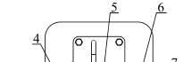
The hydraulic cylinder rod is moved by changing the direction of oil flow in the valve group of the FPTO 4 (figure 3.7.2). Oil supplied through a pressure pipeline 1, is directed either to a pipeline 2, connected with the cylinder rod end (FPTO off – rod retracted) or to a pipeline 3, connected with the bottom end of the cylinder (FPTO on – rod protracted).
1; 2, 3 – pipeline; 4 – FPTO valve group; Figure 3.7.2 – Front PTO (hydraulic part)
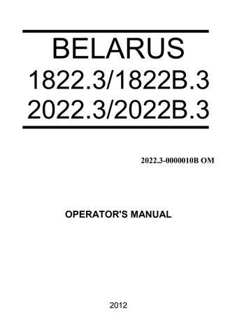
When running the FPTO for a long time, check the extraction of the control cylinder rod (dimension “ ” in figure 3.7.2). If the rod extraction value in position “FPTO off” (50±3) mm or in position “FPTO engaged” (65±3) mm does not correspond to the above stated, adjust the band brakes. To do this it is required to remove the upper cover 3 (figure 3.7.3) of the PTO reduction unit and to adjust a clearance between the turning shaft 1 and the levers 5 of the bands of the FPTO brake 6. For this reason loosen the nuts 2, turning them clockwise, to choose a clearance between the bands and the brake drums, do the screws 4 in with a torque of (5+0,5) N m, having retained horizontal position of the jaws of the shaft 1. After this release each screw 4 by 1 … 1,5 revolution and lock with nuts 2. Put the cover 3 back.
1 – shaft; 2 – nut; 3 – cover; 4 – screw; 5 – band levers; 6 – brake; 7 – protective cap. Figure 3.7.3 – Band brake adjustment


If the FPTO brake band linings have significant wear, when the above adjustment is not effective for the band brakes, replace the PTO brake bands.