4 minute read
3.8.3 Service brake adjustment of “BELARUS-1822.3/2022.3”


3.8.3 Service brake adjustment of “BELARUS-1822.3/2022.3”

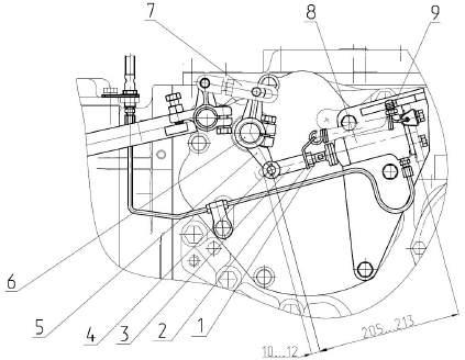
1, 2 – main cylinder; 3 – fork; 4 – nut; 5 – bolt; 6 – pin; 7 – lock-nut; 8, 9 – pedal; 10 – pipeline from main cylinder to working cylinder Figure 3.8.3 – Adjustment of pedal free play and brake pedal position
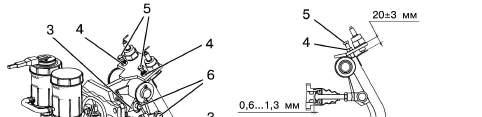
To adjust the service brakes of the tractor proceed as follows: 1. Set pads of the pedals 8, 9 (figure 3.8.3) in one plane with a help of the stop adjusting bolts 5, screwing them in to 20 3 mm. Lock the nuts 4. 2. Adjust free play of the pedals 8, 9 within 4 … 8 mm. To do this, proceed as fol-
lows:
- unsplint and remove the pins 6 and disconnect the forks 3 from the stems of the pedals 8, 9; - turn the lock-nuts 7 off by several revolutions and by screwing the forks 3 in or out, shorten or lengthen the hydraulic cylinders 1, 2 rods, to meet the required free play of the pedals; - lock the nuts 7, fit the pins 6 and cotter-pin them. The pedal free play of 4…8 mm corresponds to 0.6...1.3 mm clearance between the piston and the pusher in each main cylinder. - the pedals should not be in contact with whatever components of the cab. The height position of the pedal pads can be adjusted, if required, with the bolts 5 and by changing the length of the hydraulic cylinder rods, providing the pedal free play within 4…8 mm.
3. Set the length of working cylinder 8 (figure 3.8.4) of the left brake to 205… 213 mm, if measured from the cylinder end face to the axis of the pin 4 which connects the lever 5 with the fork 3, with the cylinder piston fully drawn in. The pin 4 stroke should be in this case within the limits of 10 …12 mm when applying force from 350 to 400 N on 60 mm arm to the lever 5. Carry out the adjustment by means of a fork 3, having performed the following operations: - disconnect the link 7 of the parking brake actuator from the lever 5; - loosen the lock-nut 2 on the cylinder rod by several turns; - turning the rod 1 of the working cylinder, adjust the cylinder length and pin stroke of the working cylinder fork within the necessary limits; - tighten the lock-nut 2, attach rod 7 of parking brake actuator.
If it is not possible to adjust necessary dimensions, it is necessary to remove the lever 5 from the brake shaft 6, having preliminary loosened the bolt of the lever 5 hub, then put it back, having turned by one spline in necessary direction (the turn by one spline changes dimensions by 8 mm). Adjust the length of right brake working cylinder in the same order.
1 – rod; 2 – lock-nut; 3 – fork; 4 – pin; 5 – lever; 6 – brake shaft; 7 – link; 8 – working cylinder; 9 – relief valve. Figure 3.8.4 – Working cylinder length adjustment
4. Bleed the hydraulic system of brake control in the following order:
- fill the tanks 3, 4 (figure 3.8.5) of the main brake cylinders 1, 2 with brake fluid to the “Max” marks on the tanks (to the level of 15 5 mm from the tank upper face). During bleeding watch the fluid level, avoiding its drop below the “Min” mark. - latch the brake pedals 5, 6 with the interlocking strap “A”. - clean the relief valves of the brake working cylinders from dust and dirt, remove the caps from them, fit a tube onto the head of the relief valve 9 (figure 3.8.4) of the left working cylinder and put its free end into a transparent reservoir with a capacity of at least 0.5 l filled with brake fluid to half of its volume; - press the interlocked brake pedals for 4…5 times and, while holding them down, turn out the relief valve 9 of the left working cylinder by 1/2 …3/4 revolution and when after a full pedal travel as a part of the fluid with air is bled from the system, turn the valve in and release the brake pedals. Press the pedal quickly, release smoothly! Repeat this operation several times until air is completely bled from the system. Remove the tube from the valve and put the protective cap. - bleed air from the hydraulic actuator of the right brake in the same order; - top up fluid in both tanks 3, 4 (figure 3.8.5) to the “Max” mark;