2 minute read
3.4 Reduction unit electro-hydraulic control


3.4 Reduction unit electro-hydraulic control
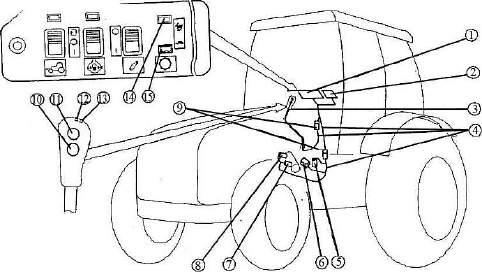
The electro-hydraulic control of the gearbox reduction unit consists of the following basic elements: - annunciators 15 and 14 (figure 3.4.2) on a control panel 1, located in the tractor
cab;
unit; - a lever 3 for shifting the speeds and the passes of the gearbox reduction unit; - a sensor of GB neutral position 5; - sensors 7 and 8, installed in the hydraulic cylinder switching the gearbox reduction
- a valve group 6, located at the top on the GB cover; - connecting cables 4 with sockets 9. The system is powered from on-board electrical line through a fuse, located in the fuse block 2. The power supply voltage is delivered to the system after the starter and instrument switch has been turned into position “I” - Instruments on”, but it is possible to shift the reduction passes only after the engine is started, with the hydraulic system pump on. On the lever 3 handle there are buttons 10 and 11 and annunciators (led-lamps) 13 and 12 of lower and higher reduction pass engagement, accordingly. On the panel 1 there are duplicate annunciators 15 and 14 of lower and higher reduction pass and reduction control relay. The systems allows switching reduction passes only with the lever 3 in neutral position (contacts of the sensor 5 of GB neutral position are closed). ATTENTION: SWITCH BETWEEN THE GB REDUCTION PASSES ONLY WITH THE TRACTOR STOPPED!
Signals to the annunciators 13, 12 and 15, 14 come from the respective pressure sensors 8 and 7. After the engine start-up the lower reduction pass turns on. Hereby the annunciators 13 and 15 must stay on. The higher reduction pass shall be switched by pressing the button 11. Hereby the annunciators 13 and 15 must go out, and the annunciators 12 and 14 must light up. Switching from the higher reduction pass to the lower one is performed by pressing the button 10. The engine can be started only when the GB range shifting lever 1 (figure 2.13.1) is set into neutral position. The electrical circuit diagram of the reduction unit electro-hydraulic control is introduced in Annex A.
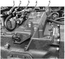
Figure 3.4.1 – Allocation of components of reduction unit electro-hydraulic control on the gearbox
To figure 3.4.1 – Allocation of components of reduction unit electro-hydraulic control on the gearbox: 1 – sensor of the lower reduction pass engaged condition; 2 – sensor of the higher reduction pass engaged condition; 3 – reduction pass switching valve group; 4 – gearbox “neutral” position sensor; 5 – sensor of range reduction neutral position (engine start-up lock with a range engaged).
1 – rear axle DL and FDA drive control panel; 2 – fuse block; 3 – lever for shifting speeds and reduction passes; 4 – connecting cables; 5 – sensor of gearbox neutral position; 6 – gearbox reduction unit valve group; 7 – pressure sensor of the higher reduction pass engaged state; 8 – pressure sensor of the lower reduction pass engaged state; 9 –carrier sockets; 10 – button to engage the lower pass; 11 – button to engage the higher pass; 12 – led-lamp to indicate the higher pass; 13 – led-lamp to indicate the lower pass; 14, 15 – pilot lamps. Figure 3.4.2 – Gearbox reduction electro-hydraulic control