2 minute read
3.2.5 Clutch case


3.2.5 Clutch case
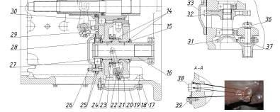
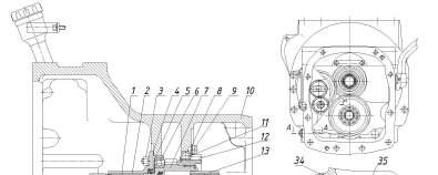
In the clutch case 10 (figure 3.2.7) a drive of a dual-speed continuous rear PTO as well as a drive of oil pumps for HLL and hydraulic system transmission are located. A driving shaft 7 of the continuous PTO drive has a toothed rim, which is in constant mesh with a gear 24, and splines, on which a gear 12 is mounted. This gear engages a gear 20 of oil pump drive, and a lock ring prevents it from axial movement. The driving shaft rotates in a roller bearing 6, mounted by means of a gasket 5 and a collar in a shifter bracket 2, which is attached to the clutch case 10 by way of threaded bolts 3 through a gasket 4. Inside the shaft 7 there is a heavy-duty a shaft 1, which transfers torque to the gearbox input shaft through a splined bushing 13. The gear 12 is mounted on the case 10 through a ball bearing 11, which is prevented from axial movement by mounting a strap 8 and bolts 9. Switching between the rear PTO modes (standard and economy) is effected by a toothed clutch 23, a lever 22 and a switching shaft 38, having flattened surfaces for the wrench. To switch between the modes it is required to loosen a securing bolt 39 and turn the shaft 38 until the clutch is engaged, after that tighten the securing bolt. To switch the standard mode it is required to turn the shaft contraclockwise until it stops, to switch the economy mode it is needed to turn the shaft clockwise until it stops. The HLL oil pump is driven through the gears 12 and 32, and the transmission hydraulic system drive – through the gears 12, 32 and shafts 31, 37. The driven gears 20, 24 are mounted through roller bearings 14 on a driven shaft 16 of the continuous PTO drive. The gear is prevented from axial movement by mounting a washer 15 and a lock ring on the shaft 16. The clutch engagement shifter is controlled by means of a fork 30, secured by a bolt 29. The BELARUS-1822.3/1822 .3 transmission has the clutch case with a drive for a single-speed continuous rear PTO for RPTO operation in a standard mode. In this connection the clutch case has its own design peculiarities: on splines of the shaft 16 (figure 3.2.7) there is only one gear 24, which is secured by the lock ring. The gear 20 as well as the parts for the rear PTO switching such as the clutch 23, the lever 22, the shaft 38 are not mounted. The clutch case has no orifice for the shaft 38 installation.
1 – heavy-duty shaft; 2 – shifter bracket; 3, 26 – threaded bolts; 4, 5, 17, 25, 34 – gaskets; 6,11, 14, 27, 35 – bearings; 7 – driving shaft; 8 – strap; 9, 18, 39 – bolts; 10 – clutch case; 12, 20, 24, 37 – gear; 13 – splined bushing; 15 – washer; 16 – driven shaft; 19, 33 – cover; 21 – securing bolt and wire; 22 – lever; 23 – toothed clutch; 28 – lock ring; 29 – securing bolt; 30 – fork; 31 –shaft-gear; 32 – pump drive gear; 36 – nut; 38 – shaft. Figure 3.2.7 – Coupling clutch case assembly