4 minute read
3.1.2 System of engine air cleaning


Nozzle 14 is intended for fuel injection into the engine cylinder. It provides the required fuel spraying and limits the beginning and end of fuel supply. Coarse-mesh filter serves for preliminary fuel purification from mechanical impurities and water. Fine filter serves for final fuel purification. While passing through shutters of the changeable paper filter cartridge, fuel is cleaned from impurities. Air inlet pipe includes an air cleaner (see subsection 3.1.2 “System of engine air cleaning”) and branch pipes connecting the air cleaner with the turbocharger, charged air cooler (see subsection 3.1.3 “System of charged air cooling”) and the inlet manifold. Under the influence of depression created by the engine turbocharger, air is cleaned from dust passing through the air cleaner, and is supplied to the turbocharger discharge chamber from which it is supplied under pressure through the charged air cooler to the engine cylinders.
Cooling system is of closed type, with forced circulation of cooling liquid from the centrifugal pump. Water pump 10 (figure 3.1.1) starts rotational movements under the influence of cone belt from crankshaft 4 pulley. Two thermostatic regulators are mounted at the delivery line in the housing of thermostatic regulators 11, and serve for speeding up of the engine warm-up after startup and automatic adjustment of temperature mode at different loads and ambient temperatures. Fan 9 of the cooling system is mounted on the shaft of water pump 10. An adjustable turbocharger using the energy of exhaust gases to boost air charging into the engine cylinders, is mounted onto engine -260.4S2 / -260.9S2. The principle of the turbocharger operation is that exhaust gases from the engine cylinders go under pressure through the outlet manifold to the turbine scroll passages. While expanding gases move the turbine wheel with the shaft, at the other end of which compressor wheel intakes air through the air cleaner and supplies it under pressure to the engine cylinders. Rotor speed, charged air supply and pressure depend on the engine operation mode. Charging adjustment is carried out by blowing-off part of exhaust gases past the turbine wheel while exceeding charging pressure of the specific value. Overflow valve is built into the turbine housing of adjustable turbocharger 6 (figure 3.1.2). The overflow valve lever is connected by means of adjustable rod with the actuating mechanism which is linked by means of the air pipeline with the compressor outlet. Regulator adjustment for specific pressure is carried out by the rod length adjustment. Changing of the rod length of the turbocharger actuating mechanism during the operation process is not allowed! The device of the engine startup consists of electric starter 20 with rated voltage of 24V. The starter is a direct current motor with compound excitation having an electromagnetic relay and the drive mechanism. To provide startup at low ambient temperature all engines are equipped with heating plugs 19 with rated voltage of 23V. Alternator serves for AB recharge and also for direct current supply to all electric energy consumers mounted on the tractor. Alternator drive is carried out by means of the cone belt from the crankshaft pulley. The alternator is mounted on the engine right side above the HSC operating pump. To provide the trailer pneumatic brakes drive and tire inflation, tractor engine is equipped with the piston single-stage pneumatic compressor of air cooling. The compressor is mounted on the distributor cap flange and has a drive from the compressor drive gear of the distribution mechanism. To provide HSC operation, a gear-type pump is mounted on the engine. The pump starts rotating under the influence of the drive from engine timing gears. The HSC operating pump is mounted on the right side of the engine, under the alternator.
3.1.2 System of engine air cleaning
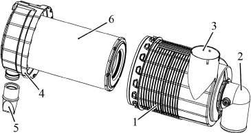
The “BELARUS-1822.3/1822 .3/2022.3/2022 .3” tractor has an air purifier of “Donaldson” company FPG100318 of dry type using one paper filtering element P781039. This air purifier has two stages of cleaning: - preliminary inertia air cleaning (in-built cyclone). It is carried out inside the air purifier at the cost of tangential intake and centrifugal forces, emerging by air spiral rotation with relation to the axis of the case 1 (figure 3.1.4) of the air purifier. Dust is discharged through a rubber valve 5, mounted on the cover 4 of the air purifier, as the engine is stopped and started, at the cost of excess pressure, emerging inside the air purifier; - dry cleaning with a main filtering element 6. Air is fed through the air intake 3. Air is delivered to the turbocharger through the air pipeline by means of a delivery pipe 2.
1 – case; 2 – delivery pipe; 3 – air intake; 4 – cover; 5 – rubber valve; 6 – main filtering element (MFE).
Figure 3.1.4 – Air purifier To indicate the air cleaner impurity there is a pilot lamp, located in the pilot lamp unit of the instrument dashboard. An electronic sensor of air cleaner impurity is mounted in the area of air delivery pipeline and responses as discharging reaches 7 kPa.