Belarus 1822.3 1822B.3 2022.3 2022B.3 Operator's Manual - PDF DOWNLOAD

Page 89

2022.3-0000010 OM

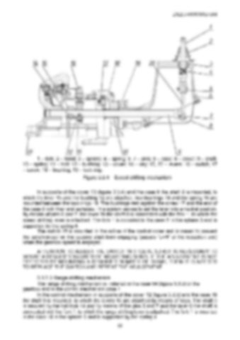
1 – fork; 2 – hood; 3 – sphere; 4 – spring; 5, 7 – pins; 6 – case; 8 – cover; 9 – shaft; 10 – spring; 11 – bolt; 12 – bushing; 13 – cover; 14 – key; 15, 20 – levers; 16 – switch; 17 – screw; 18 – bushing; 19 – lock ring. Figure 3.3.4 – Speed shifting mechanism In supports of the cover 13 (figure 3.3.4) and the case 6 the shaft 9 is mounted, to which the lever 15 and the bushing 12 are attached; two bushings 18 and the spring 10 are mounted between the lock rings 19. The bushings rest against the screw 17 and the end of the case 6 with their end surfaces. This system serves to set the lever into a neutral position. By means of pins 5 and 7, the lever 20 the shaft 9 is connected with the fork 1, to which the speed shifting lever is attached. The fork 1 is mounted in the case 6 in the sphere 3 and is supported by the spring 4. The switch 16 is mounted in the orifice of the control cover and is meant to prevent the synchronizer on the second shaft from engaging (passes “L=H” of the reduction unit) when the gearbox speed is engaged. ATTENTION: TO ADJUST THE SWITCH 16 (FIGURE 3.3.4) IT IS NECESSARY TO MOUNT A REQUIRED NUMBER OF ADJUSTING SHIMS. IF THE ADJUSTMENT IS NOT EFFECTED BY MOUNTING A REQUIRED NUMBER OF SHIMS, THEN IT IS NEEDED TO REPLACE THE SWITCH AND REPEAT THE ADJUSTMENT. 3.3.3.3 Range shifting mechanism The range shifting mechanism is installed in the case 54 (figure 3.3.2) of the gearbox and in the control mechanism case 1. In the control mechanism in supports of the cover 12 (figure 3.3.5) and the case 18 the shaft 9 is mounted, to which the levers 10 are attached by means of keys. The shaft 9 is secured by the ball lock 14 and by means of the pins 5 and 7 and the laver 6 the shaft is connected with the fork 1, to which the range shifting lever is attached. The fork 1 is mounted in the case 18 in the sphere 3 and is supported by the spring 4. 88


Turn static files into dynamic content formats.

Create a flipbook

Articles inside

10. TRACTOR DISPOSAL

1min
page 352

8.8 Safety requirements for preservation

1min
page 350

8.5 Preservation

2min
page 348

troubleshooting

4min
pages 344-346

washer, acoustic alarm

2min
page 336

7.15.3 Search and elimination of failures in engine start-up system

4min
pages 332-333

7.15.5 Search and elimination of failures in air conditioner electrics

3min
page 335

7.15.4 Search and elimination of failures in lighting facilities

3min
page 334

7.14.3 Section R-23LS lowering valve disassembly procedure

1min
page 329

troubleshooting

8min
pages 321-326

7.11 Possible failures of FDA and guidelines for troubleshooting

8min
pages 315-320

troubleshooting

1min
page 314

7.9 Possible failures in pneumatic system and guidelines for troubleshooting

3min
pages 312-313

7.8 Possible failures of brakes and guidelines for troubleshooting

5min
pages 309-311

7.7 Possible failures in front power take-off shaft and guidelines for troubleshooting

1min
page 308

troubleshooting

3min
pages 305-306

3.13 Undercarriage and tractor wheels

1min
page 129

3.12.3 Front PTO control

1min
page 128

3.12.2 FDA drive control

1min
page 127

3.11.4.2 Adjustment of FDA drive automatic switch

2min
page 125

3.11.3 Wheel gear group

2min
pages 122-123

3.9.5 Check and adjustment of pneumatic system pressure regulator

1min
page 118

system

1min
page 117

3.9.3 Double-line pneumatic drive of trailer brakes

2min
page 113

3.8.6 Parking brake

2min
page 110

3.8.7 Parking brake adjustment

1min
page 111

3.8.5 Service brake adjustment of “BELARUS-1822 .3/2022 .3”

1min
page 109

3.8.4 Service brake control of “BELARUS-1822 .3/2022 .3”

3min
pages 107-108

3.7 Front power takeoff shaft

3min
pages 101-102

3.8.3 Service brake adjustment of “BELARUS-1822.3/2022.3”

4min
pages 105-106

3.8.2 Service brake control of “BELARUS-1822.3/2022.3”

1min
page 104

3.6.2 Rear PTO control

2min
page 100

3.5.6 Rear axle final drive adjustment

2min
page 96

3.4 Reduction unit electro-hydraulic control

2min
pages 92-93

reduction unit

2min
page 90

3.3.3.5 Gearbox control

1min
page 91

3.1.4 Engine cooling system

1min
page 75

3.1.2 System of engine air cleaning

4min
pages 72-73

3.2.4.3 Clutch check for purity of disengagement

2min
page 82

3.1.3 System of charged air cooling

1min
page 74

3.3.3.3 Range shifting mechanism

1min
page 89

3.2.5 Clutch case

2min
page 83

3.1.1.2 Engine elements

8min
pages 68-71

2.24 Fuel tank valve control

1min
page 66

2.19.3 BELARUS seat installation for operation on reverse

1min
page 60

2.18.4 Cab hatch opening

1min
page 58

2.23 Reverse post controls of BELARUS-1822 .3/2022 .3

2min
pages 64-65

2.17.2 Fuses for electrical equipment system

3min
pages 53-55

2.17.3 Fuses of electronic control systems

1min
page 56

2.19.4 “Grammer” seat adjustments

1min
page 61
Issuu converts static files into: digital portfolios, online yearbooks, online catalogs, digital photo albums and more. Sign up and create your flipbook.
Belarus 1822.3 1822B.3 2022.3 2022B.3 Operator's Manual - PDF DOWNLOAD by www.heydownloads.com - Issuu