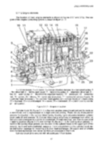
2022.3-0000010 OM 3.1.1.2 Engine elements The location of main engine elements is shown in figures 3.1.1 and 3.1.2. The diagram of the engine lubricating system is shown in figure 3.1.3.
1 – oil crankcase; 2 – oil pump; 3 – torque vibration damper; 4 – crankshaft pulley; 5 – fan drive belt; 6 – timing gear cover; 7 – tensioning pulley; 8 – alternator drive belt; 9 – fan; 10 – water pump; 11 – thermostatic regulator housing; 12 – piston pin; 1 – connector rod, 14 – piston; 15 – sleeve; 16 – cover cap (2 pieces); 17 – covers for cylinder heads; 18 – cylinder head (2 pieces.), 19 – cylinder head gasket; 20 – cylinder block; 21 – back plate; 22 – flywheel; 23 – counterweight; 24 – cover; 25 – crankshaft; 26 – piston cooling nozzle; 27 – oil receiver. Figure 3.1.1 – Engine in section Cylinder block 20 (figure 3.1.1) is the main engine case-shaped part and is made as a monoblock and is represented as a rigid cast-iron casting. There are six dismountable sleeves 15 installed in the cylinder block bores. Cooling liquid circulates between cylinder block walls 20 and sleeves 15. Cylinder block has a lengthway oil passage from which oil through cross passages is supplied to crankshaft 25 main bearings, and then to cam shaft 1 bearing journals (figure 3.1.2) and nozzles 26 (figure 3.1.1) for cooling down pistons 14. Nozzles for cooling down pistons are mounted in the cylinder block in the upper part of the second, fourth and sixth crankshaft supports. There is a platform on the cylinder block water-distribution passage for mounting a fluid-oil heat-exchanger. Oil supply and oil offtake from the heat-exchanger are carried out through passages in the block. Cylinder block 20 is covered with oil crankcase 1 from below. 67


