Belarus 1822.3 1822B.3 2022.3 2022B.3 Operator's Manual - PDF DOWNLOAD

Page 125

2022.3-0000010 OM As the rear wheel skidding exceeds the preset value, the shaft 6 speed decreases to such extent that the drum 3 turns in an opposite direction and the spring 5 returns the half-clutch 4 into its initial position. The half-clutch displaces the pusher 12 with its tapered part, the switch 13 closes the electrical circuit of the hydraulic valve group 11 electromagnet, oil is supplied to the clutch booster under pressure, thus moving the piston 2. Hereby the disk pack gets compressed, locking the gear 1 and the drum 3 and ensuring torque transfer. As the FDA is positively engaged, oil is supplied to the clutch booster irrespective of the rear wheel skidding. As the FDA is disengaged the valve group overlaps the charging line, and oil goes from the clutch booster for drain. For checking pressure in the drive clutch booster there is a testing hole, shut with a plug 14. The switch 13 and the electro-hydraulic valve group 11 are guarded with a housing 10. Rules for FDA drive control are provided in section 2 “Controls and instruments”. 3.11.4.2 Adjustment of FDA drive automatic switch

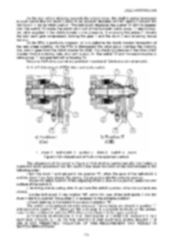
1 – drum; 2 – half-clutch; 3 – pusher; 4 – shim; 5 – switch; 6 – cover. Figure 3.11.6 – Adjustment of FDA drive automatic switch

The adjustment of the switch 5 (figure 3.11.6) shall be carried out after the hydraulic clutch has been assembled and the cover 6 has been mounted on the transmission in the following order: - turn the drum 1 and set put it into position “I”, when the jaws of the half-clutch 2 and the drum 1 are fully closed, the pusher 3 is projected into the extreme position; - mount the initial number of the adjusting shims 4 (five or six pieces) under the end surface of the switch 5; - removing one adjusting shim 4, achieve the switch position, when its contacts are closed; - put the half-clutch 2 into position “II”, when the jaws of the half-clutch 2 and the drum 1 are fully opened, the pusher 3 is recessed to the extreme position; - check opening of the switch 5 contacts in position “II”. The switch is considered correctly adjusted if its contacts are closed in position “I” and opened in position “II”. Check per the pilot lamp. It is possible to check per the annunciator on the dashboard, with the FDA drive control button in the upper position. ATTENTION: IN POSITION “I” THE DIMENSION “A” FROM THE PUSHER 3 END SURFACE (FIGURE 3.11.6) TO THE SWITCH 5 END SURFACE BEING BELOW 11,5 MM IS NOT PREMITTED! VIOLATION OF THIS REQUIREMENT MAY RESULT IN SWITCH BREAKDOWN! 124


Turn static files into dynamic content formats.

Create a flipbook

Articles inside

10. TRACTOR DISPOSAL

1min
page 352

8.8 Safety requirements for preservation

1min
page 350

8.5 Preservation

2min
page 348

troubleshooting

4min
pages 344-346

washer, acoustic alarm

2min
page 336

7.15.3 Search and elimination of failures in engine start-up system

4min
pages 332-333

7.15.5 Search and elimination of failures in air conditioner electrics

3min
page 335

7.15.4 Search and elimination of failures in lighting facilities

3min
page 334

7.14.3 Section R-23LS lowering valve disassembly procedure

1min
page 329

troubleshooting

8min
pages 321-326

7.11 Possible failures of FDA and guidelines for troubleshooting

8min
pages 315-320

troubleshooting

1min
page 314

7.9 Possible failures in pneumatic system and guidelines for troubleshooting

3min
pages 312-313

7.8 Possible failures of brakes and guidelines for troubleshooting

5min
pages 309-311

7.7 Possible failures in front power take-off shaft and guidelines for troubleshooting

1min
page 308

troubleshooting

3min
pages 305-306

3.13 Undercarriage and tractor wheels

1min
page 129

3.12.3 Front PTO control

1min
page 128

3.12.2 FDA drive control

1min
page 127

3.11.4.2 Adjustment of FDA drive automatic switch

2min
page 125

3.11.3 Wheel gear group

2min
pages 122-123

3.9.5 Check and adjustment of pneumatic system pressure regulator

1min
page 118

system

1min
page 117

3.9.3 Double-line pneumatic drive of trailer brakes

2min
page 113

3.8.6 Parking brake

2min
page 110

3.8.7 Parking brake adjustment

1min
page 111

3.8.5 Service brake adjustment of “BELARUS-1822 .3/2022 .3”

1min
page 109

3.8.4 Service brake control of “BELARUS-1822 .3/2022 .3”

3min
pages 107-108

3.7 Front power takeoff shaft

3min
pages 101-102

3.8.3 Service brake adjustment of “BELARUS-1822.3/2022.3”

4min
pages 105-106

3.8.2 Service brake control of “BELARUS-1822.3/2022.3”

1min
page 104

3.6.2 Rear PTO control

2min
page 100

3.5.6 Rear axle final drive adjustment

2min
page 96

3.4 Reduction unit electro-hydraulic control

2min
pages 92-93

reduction unit

2min
page 90

3.3.3.5 Gearbox control

1min
page 91

3.1.4 Engine cooling system

1min
page 75

3.1.2 System of engine air cleaning

4min
pages 72-73

3.2.4.3 Clutch check for purity of disengagement

2min
page 82

3.1.3 System of charged air cooling

1min
page 74

3.3.3.3 Range shifting mechanism

1min
page 89

3.2.5 Clutch case

2min
page 83

3.1.1.2 Engine elements

8min
pages 68-71

2.24 Fuel tank valve control

1min
page 66

2.19.3 BELARUS seat installation for operation on reverse

1min
page 60

2.18.4 Cab hatch opening

1min
page 58

2.23 Reverse post controls of BELARUS-1822 .3/2022 .3

2min
pages 64-65

2.17.2 Fuses for electrical equipment system

3min
pages 53-55

2.17.3 Fuses of electronic control systems

1min
page 56

2.19.4 “Grammer” seat adjustments

1min
page 61
Issuu converts static files into: digital portfolios, online yearbooks, online catalogs, digital photo albums and more. Sign up and create your flipbook.