Belarus 1822.3 1822B.3 2022.3 2022B.3 Operator's Manual - PDF DOWNLOAD

Page 122

2022.3-0000010 OM

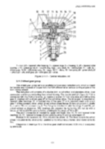
1 – nut; 2,4 – tapered roller bearing; 3 – spacer rings; 5 – housing; 6, 24 – tapered roller bearing; 7,19 – adjusting nut; 8 – level/fill plug; 9,22 – axle shaft; 10 – locking bolt; 11 – bolt; 12 – driven gear; 13,14 – differential case; 15 – cage; 16,17 – disks; 18 – lock plate; 20 – pinion shaft; 21 – pinion; 23 – axle shaft gear; 25 – drive gear; 26 – collar. Figure 3.11.2 – Central reduction unit 3.11.3 Wheel gear group The wheel gear group set is a parallel-shaft planetary reduction unit, which is meant for transfer and increase of torque from the FDA differential at various turning angles of the front driving wheels. The reduction unit consists of a double joint, a cylindrical and planetary drive, pivot connection and levers controlling front wheel turning. The double joint 21 (figure 3.11.3) is connected with the FDA differential by means of a shaft 17 from one side, and with a drive gear 9, meshed with a driven gear 27 of the cylindrical drive. The drive gear is mounted on tapered roller bearings 10. A toothed ring of the gear 27 is in constant mesh with a sun gear 2 of the planetary drive, which drives a front wheel flange 30 through pinions 4, shafts 3, a carrier 29 and a crown ring 5. The flange is installed in roller bearings 1 and 25, adjusted without a clearance. The bearings are adjusted by tightening the nut 32 with a torque of 180 to 200 Nm and its further undoing by the angle of 15 to 20°. The pivot connection is created by upper and lower pins 14, 24 and tapered roller bearings 16, 23, installed in bores of a knuckle housing 26 and an axle beam 18. Preload in the bearings 16, 23 is adjusted by shims 15. The force to turn the wheel group in relation to the pivot center, applied to the wheel group flange, shall make 60 to 80 Nm. Clearance in bearings 10 of the drive gear shall not exceed 0.05 mm, it is adjusted by shims 22.

121


Turn static files into dynamic content formats.

Create a flipbook

Articles inside

10. TRACTOR DISPOSAL

1min
page 352

8.8 Safety requirements for preservation

1min
page 350

8.5 Preservation

2min
page 348

troubleshooting

4min
pages 344-346

washer, acoustic alarm

2min
page 336

7.15.3 Search and elimination of failures in engine start-up system

4min
pages 332-333

7.15.5 Search and elimination of failures in air conditioner electrics

3min
page 335

7.15.4 Search and elimination of failures in lighting facilities

3min
page 334

7.14.3 Section R-23LS lowering valve disassembly procedure

1min
page 329

troubleshooting

8min
pages 321-326

7.11 Possible failures of FDA and guidelines for troubleshooting

8min
pages 315-320

troubleshooting

1min
page 314

7.9 Possible failures in pneumatic system and guidelines for troubleshooting

3min
pages 312-313

7.8 Possible failures of brakes and guidelines for troubleshooting

5min
pages 309-311

7.7 Possible failures in front power take-off shaft and guidelines for troubleshooting

1min
page 308

troubleshooting

3min
pages 305-306

3.13 Undercarriage and tractor wheels

1min
page 129

3.12.3 Front PTO control

1min
page 128

3.12.2 FDA drive control

1min
page 127

3.11.4.2 Adjustment of FDA drive automatic switch

2min
page 125

3.11.3 Wheel gear group

2min
pages 122-123

3.9.5 Check and adjustment of pneumatic system pressure regulator

1min
page 118

system

1min
page 117

3.9.3 Double-line pneumatic drive of trailer brakes

2min
page 113

3.8.6 Parking brake

2min
page 110

3.8.7 Parking brake adjustment

1min
page 111

3.8.5 Service brake adjustment of “BELARUS-1822 .3/2022 .3”

1min
page 109

3.8.4 Service brake control of “BELARUS-1822 .3/2022 .3”

3min
pages 107-108

3.7 Front power takeoff shaft

3min
pages 101-102

3.8.3 Service brake adjustment of “BELARUS-1822.3/2022.3”

4min
pages 105-106

3.8.2 Service brake control of “BELARUS-1822.3/2022.3”

1min
page 104

3.6.2 Rear PTO control

2min
page 100

3.5.6 Rear axle final drive adjustment

2min
page 96

3.4 Reduction unit electro-hydraulic control

2min
pages 92-93

reduction unit

2min
page 90

3.3.3.5 Gearbox control

1min
page 91

3.1.4 Engine cooling system

1min
page 75

3.1.2 System of engine air cleaning

4min
pages 72-73

3.2.4.3 Clutch check for purity of disengagement

2min
page 82

3.1.3 System of charged air cooling

1min
page 74

3.3.3.3 Range shifting mechanism

1min
page 89

3.2.5 Clutch case

2min
page 83

3.1.1.2 Engine elements

8min
pages 68-71

2.24 Fuel tank valve control

1min
page 66

2.19.3 BELARUS seat installation for operation on reverse

1min
page 60

2.18.4 Cab hatch opening

1min
page 58

2.23 Reverse post controls of BELARUS-1822 .3/2022 .3

2min
pages 64-65

2.17.2 Fuses for electrical equipment system

3min
pages 53-55

2.17.3 Fuses of electronic control systems

1min
page 56

2.19.4 “Grammer” seat adjustments

1min
page 61
Issuu converts static files into: digital portfolios, online yearbooks, online catalogs, digital photo albums and more. Sign up and create your flipbook.