Belarus 1822.3 1822B.3 2022.3 2022B.3 Operator's Manual - PDF DOWNLOAD

Page 118

2022.3-0000010 OM 3.9.5 Check and adjustment of pneumatic system pressure regulator It is necessary to adjust the pneumatic system pressure regulator during maintenance MS3, and also when the pressure regulator operation is disturbed as well as after its disassembly for washing or for replacement of worn out parts. Check and adjustment of the pneumatic system pressure regulator should be made after adjustment of service brake control, of parking brake control and brake valve actuator. Check the pneumatic system pressure regulator in the following order: - connect the pressure gage (with scale factor of 0,01 …0,02 MPa and scale at least up to1,6 MPa) to the connecting head with red cover; - take off a cap 1 (figure 3.9.6); - using a wrench screw a cover 2 to the casing against the stop; - turn the pneumatic compressor on; - start the engine and fill the tank with compressed air until a safety valve 7 is actuated at pressure of 0.85… 1 MPa. If the valve is actuated at pressure less than 0.85 MPa or more than 1 MPa, make its adjustment with a screw 9, having previously loosened and then having tightened a lock-nut 8. Adjust the pneumatic system pressure regulator in the following order: - gradually unscrewing of the cover 2, adjust force of springs 3 and 4 so that air pressure in the tank, at which a relief valve 6 opens, made 0.77 to 0.8 MPa; - mark this position of the cover 2 using paint applied on a treaded part of the casing and put the cap 1; - slightly open the condensate drain valve in the tank and reduce air pressure to 0.65 …0.7 MPa. At this pressure values the valve 6 should close and switch the pneumatic compressor over to tank filling with compressed air; - disconnect the test pressure gage from the connecting head.

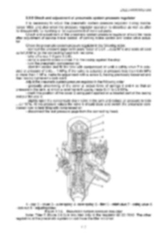
1 – cap; 2 – cover; 3 – outer spring; 4 –inner spring; 5 – filter; 6 – relief valve; 7 – safety valve; 8 – lock-nut; 9 – adjusting screw. Figure 3.9.6 – Pneumatic system pressure regulator Note: Filter 5 (figure 3.9.6) is mounted only in the regulator 80-3512010. The other regulators of the pneumatic system do not have the filter mounted. 117


Turn static files into dynamic content formats.

Create a flipbook

Articles inside

10. TRACTOR DISPOSAL

1min
page 352

8.8 Safety requirements for preservation

1min
page 350

8.5 Preservation

2min
page 348

troubleshooting

4min
pages 344-346

washer, acoustic alarm

2min
page 336

7.15.3 Search and elimination of failures in engine start-up system

4min
pages 332-333

7.15.5 Search and elimination of failures in air conditioner electrics

3min
page 335

7.15.4 Search and elimination of failures in lighting facilities

3min
page 334

7.14.3 Section R-23LS lowering valve disassembly procedure

1min
page 329

troubleshooting

8min
pages 321-326

7.11 Possible failures of FDA and guidelines for troubleshooting

8min
pages 315-320

troubleshooting

1min
page 314

7.9 Possible failures in pneumatic system and guidelines for troubleshooting

3min
pages 312-313

7.8 Possible failures of brakes and guidelines for troubleshooting

5min
pages 309-311

7.7 Possible failures in front power take-off shaft and guidelines for troubleshooting

1min
page 308

troubleshooting

3min
pages 305-306

3.13 Undercarriage and tractor wheels

1min
page 129

3.12.3 Front PTO control

1min
page 128

3.12.2 FDA drive control

1min
page 127

3.11.4.2 Adjustment of FDA drive automatic switch

2min
page 125

3.11.3 Wheel gear group

2min
pages 122-123

3.9.5 Check and adjustment of pneumatic system pressure regulator

1min
page 118

system

1min
page 117

3.9.3 Double-line pneumatic drive of trailer brakes

2min
page 113

3.8.6 Parking brake

2min
page 110

3.8.7 Parking brake adjustment

1min
page 111

3.8.5 Service brake adjustment of “BELARUS-1822 .3/2022 .3”

1min
page 109

3.8.4 Service brake control of “BELARUS-1822 .3/2022 .3”

3min
pages 107-108

3.7 Front power takeoff shaft

3min
pages 101-102

3.8.3 Service brake adjustment of “BELARUS-1822.3/2022.3”

4min
pages 105-106

3.8.2 Service brake control of “BELARUS-1822.3/2022.3”

1min
page 104

3.6.2 Rear PTO control

2min
page 100

3.5.6 Rear axle final drive adjustment

2min
page 96

3.4 Reduction unit electro-hydraulic control

2min
pages 92-93

reduction unit

2min
page 90

3.3.3.5 Gearbox control

1min
page 91

3.1.4 Engine cooling system

1min
page 75

3.1.2 System of engine air cleaning

4min
pages 72-73

3.2.4.3 Clutch check for purity of disengagement

2min
page 82

3.1.3 System of charged air cooling

1min
page 74

3.3.3.3 Range shifting mechanism

1min
page 89

3.2.5 Clutch case

2min
page 83

3.1.1.2 Engine elements

8min
pages 68-71

2.24 Fuel tank valve control

1min
page 66

2.19.3 BELARUS seat installation for operation on reverse

1min
page 60

2.18.4 Cab hatch opening

1min
page 58

2.23 Reverse post controls of BELARUS-1822 .3/2022 .3

2min
pages 64-65

2.17.2 Fuses for electrical equipment system

3min
pages 53-55

2.17.3 Fuses of electronic control systems

1min
page 56

2.19.4 “Grammer” seat adjustments

1min
page 61
Issuu converts static files into: digital portfolios, online yearbooks, online catalogs, digital photo albums and more. Sign up and create your flipbook.