Belarus 1822.3 1822B.3 2022.3 2022B.3 Operator's Manual - PDF DOWNLOAD

Page 113

2022.3-0000010 OM tor; 9 – emergency air pressure lamp; 10 – pressure sensor; 11 – emergency pressure sensor; 12 – tank; 13 – condensate drain valve. Figure 3.9.1 – Single-line pneumatic drive of trailer brakes Air is fed to the compressor 1 (figure 3.9.1) from the engine intake manifold through the line 2. The air is compressed in the compressor 1 and delivered through the pressure regulator 3 to the tank 12, from which the compressed air is fed to the brake valve 5. With the brake pedals not pressed air goes to the connecting head 7 through the brake valve 5 and the control line 6 and further to the trailer brake pneumatic drive. The pressure regulator 3 has an air bleed valve 4, which is used for tire inflation. Air pressure in the tanks 12 is controlled by the air pressure indicator 8 with an emergency air pressure lamp 9 (red color) in the instrument cluster as well as by pressure sensors 10 and emergency pressure sensors 11. To remove the condensate from the tank 12 there is a valve 13. The connecting head 7 is valve-type. The valve prevents compressed air from going out when using the pneumatic drive without a trailer attached (when inflating tires). The trailer brakes are controlled in two modes: direct and automatic. The direct control of the brakes is performed by means of pressure drop in the connecting line 6 when the tractor decelerates. In such case, delivery of compressed air to the trailer pneumatic system stops. The automatic control of the trailer brakes is performed in case of emergency disconnection of the trailer and the tractor due to pressure drop to zero in the trailer connecting line. Note – Rules on checking and adjustment of the brake valve of the single-line pneumatic drive are given in clause 3.9.4.2.2. 3.9.3 Double-line pneumatic drive of trailer brakes The double-line pneumatic drive provides controlling brakes of trailers and agricultural machines, equipped with double-line pneumatic brake drives, as well as tire inflation. A diagram for the double-line pneumatic drive is shown in figure 3.9.2.

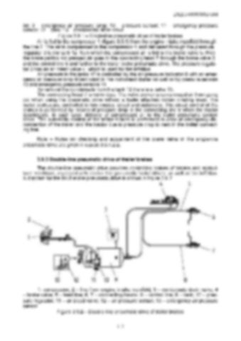
1- compressor; 2 – line from engine intake manifold; 3 – condensate drain valve; 4 – brake valve; 5 – feed line; 6, 7 – connecting heads; 8 – control line; 9 – tank; 10 – pressure regulator; 11 – air bleed valve; 12 – air pressure sensor; 13 – emergency air pressure sensor. Figure 3.9.2 – Double-line pneumatic drive of trailer brakes 112


Turn static files into dynamic content formats.

Create a flipbook

Articles inside

10. TRACTOR DISPOSAL

1min
page 352

8.8 Safety requirements for preservation

1min
page 350

8.5 Preservation

2min
page 348

troubleshooting

4min
pages 344-346

washer, acoustic alarm

2min
page 336

7.15.3 Search and elimination of failures in engine start-up system

4min
pages 332-333

7.15.5 Search and elimination of failures in air conditioner electrics

3min
page 335

7.15.4 Search and elimination of failures in lighting facilities

3min
page 334

7.14.3 Section R-23LS lowering valve disassembly procedure

1min
page 329

troubleshooting

8min
pages 321-326

7.11 Possible failures of FDA and guidelines for troubleshooting

8min
pages 315-320

troubleshooting

1min
page 314

7.9 Possible failures in pneumatic system and guidelines for troubleshooting

3min
pages 312-313

7.8 Possible failures of brakes and guidelines for troubleshooting

5min
pages 309-311

7.7 Possible failures in front power take-off shaft and guidelines for troubleshooting

1min
page 308

troubleshooting

3min
pages 305-306

3.13 Undercarriage and tractor wheels

1min
page 129

3.12.3 Front PTO control

1min
page 128

3.12.2 FDA drive control

1min
page 127

3.11.4.2 Adjustment of FDA drive automatic switch

2min
page 125

3.11.3 Wheel gear group

2min
pages 122-123

3.9.5 Check and adjustment of pneumatic system pressure regulator

1min
page 118

system

1min
page 117

3.9.3 Double-line pneumatic drive of trailer brakes

2min
page 113

3.8.6 Parking brake

2min
page 110

3.8.7 Parking brake adjustment

1min
page 111

3.8.5 Service brake adjustment of “BELARUS-1822 .3/2022 .3”

1min
page 109

3.8.4 Service brake control of “BELARUS-1822 .3/2022 .3”

3min
pages 107-108

3.7 Front power takeoff shaft

3min
pages 101-102

3.8.3 Service brake adjustment of “BELARUS-1822.3/2022.3”

4min
pages 105-106

3.8.2 Service brake control of “BELARUS-1822.3/2022.3”

1min
page 104

3.6.2 Rear PTO control

2min
page 100

3.5.6 Rear axle final drive adjustment

2min
page 96

3.4 Reduction unit electro-hydraulic control

2min
pages 92-93

reduction unit

2min
page 90

3.3.3.5 Gearbox control

1min
page 91

3.1.4 Engine cooling system

1min
page 75

3.1.2 System of engine air cleaning

4min
pages 72-73

3.2.4.3 Clutch check for purity of disengagement

2min
page 82

3.1.3 System of charged air cooling

1min
page 74

3.3.3.3 Range shifting mechanism

1min
page 89

3.2.5 Clutch case

2min
page 83

3.1.1.2 Engine elements

8min
pages 68-71

2.24 Fuel tank valve control

1min
page 66

2.19.3 BELARUS seat installation for operation on reverse

1min
page 60

2.18.4 Cab hatch opening

1min
page 58

2.23 Reverse post controls of BELARUS-1822 .3/2022 .3

2min
pages 64-65

2.17.2 Fuses for electrical equipment system

3min
pages 53-55

2.17.3 Fuses of electronic control systems

1min
page 56

2.19.4 “Grammer” seat adjustments

1min
page 61
Issuu converts static files into: digital portfolios, online yearbooks, online catalogs, digital photo albums and more. Sign up and create your flipbook.