Belarus 1822.3 1822B.3 2022.3 2022B.3 Operator's Manual - PDF DOWNLOAD

Page 104

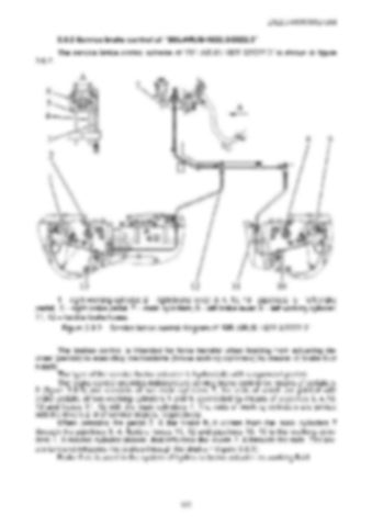
2022.3-0000010 OM 3.8.2 Service brake control of “BELARUS-1822.3/2022.3” The service brake control scheme of “BELARUS-1822.3/2022.3” is shown in figure 3.8.2.

1 – right working cylinder; 2 – right brake lever; 3, 4, 10, 13 - pipelines; 5 – left brake pedal; 6 – right brake pedal; 7 – main cylinders; 8 – left brake lever; 9 – left working cylinder; 11, 12 – flexible brake hoses. Figure 3.8.2 – Service brake control diagram of “BELARUS-1822.3/2022.3” The brakes control is intended for force transfer when braking from actuating devices (pedals) to executing mechanisms (brake working cylinders) by means of brake fluid supply. The type of the service brake actuator is hydrostatic with suspended pedals. The brake control provides independent service brake control by means of pedals 5, 6 (figure 3.8.2) and consists of two main cylinders 7, the rods of which are jointed with brake pedals; of two working cylinders 1 and 9, connected by means of pipelines 3, 4,10, 13 and hoses 11, 12 with the main cylinders 7. The rods of working cylinders are jointed with the levers 2, 8 of service brakes, respectively. When pressing the pedal 5, 6 the brake fluid comes from the main cylinders 7 through the pipelines 3, 4, flexible hoses 11, 12 and pipelines 10, 13 to the working cylinders 1, 9 moving cylinder pistons, that influence the levers 2, 8 through the rods. The levers turn and influence the brakes through the shafts 7 (figure 3.8.1). Brake fluid is used in the system of hydraulic brake actuator as working fluid.

103


Turn static files into dynamic content formats.

Create a flipbook

Articles inside

10. TRACTOR DISPOSAL

1min
page 352

8.8 Safety requirements for preservation

1min
page 350

8.5 Preservation

2min
page 348

troubleshooting

4min
pages 344-346

washer, acoustic alarm

2min
page 336

7.15.3 Search and elimination of failures in engine start-up system

4min
pages 332-333

7.15.5 Search and elimination of failures in air conditioner electrics

3min
page 335

7.15.4 Search and elimination of failures in lighting facilities

3min
page 334

7.14.3 Section R-23LS lowering valve disassembly procedure

1min
page 329

troubleshooting

8min
pages 321-326

7.11 Possible failures of FDA and guidelines for troubleshooting

8min
pages 315-320

troubleshooting

1min
page 314

7.9 Possible failures in pneumatic system and guidelines for troubleshooting

3min
pages 312-313

7.8 Possible failures of brakes and guidelines for troubleshooting

5min
pages 309-311

7.7 Possible failures in front power take-off shaft and guidelines for troubleshooting

1min
page 308

troubleshooting

3min
pages 305-306

3.13 Undercarriage and tractor wheels

1min
page 129

3.12.3 Front PTO control

1min
page 128

3.12.2 FDA drive control

1min
page 127

3.11.4.2 Adjustment of FDA drive automatic switch

2min
page 125

3.11.3 Wheel gear group

2min
pages 122-123

3.9.5 Check and adjustment of pneumatic system pressure regulator

1min
page 118

system

1min
page 117

3.9.3 Double-line pneumatic drive of trailer brakes

2min
page 113

3.8.6 Parking brake

2min
page 110

3.8.7 Parking brake adjustment

1min
page 111

3.8.5 Service brake adjustment of “BELARUS-1822 .3/2022 .3”

1min
page 109

3.8.4 Service brake control of “BELARUS-1822 .3/2022 .3”

3min
pages 107-108

3.7 Front power takeoff shaft

3min
pages 101-102

3.8.3 Service brake adjustment of “BELARUS-1822.3/2022.3”

4min
pages 105-106

3.8.2 Service brake control of “BELARUS-1822.3/2022.3”

1min
page 104

3.6.2 Rear PTO control

2min
page 100

3.5.6 Rear axle final drive adjustment

2min
page 96

3.4 Reduction unit electro-hydraulic control

2min
pages 92-93

reduction unit

2min
page 90

3.3.3.5 Gearbox control

1min
page 91

3.1.4 Engine cooling system

1min
page 75

3.1.2 System of engine air cleaning

4min
pages 72-73

3.2.4.3 Clutch check for purity of disengagement

2min
page 82

3.1.3 System of charged air cooling

1min
page 74

3.3.3.3 Range shifting mechanism

1min
page 89

3.2.5 Clutch case

2min
page 83

3.1.1.2 Engine elements

8min
pages 68-71

2.24 Fuel tank valve control

1min
page 66

2.19.3 BELARUS seat installation for operation on reverse

1min
page 60

2.18.4 Cab hatch opening

1min
page 58

2.23 Reverse post controls of BELARUS-1822 .3/2022 .3

2min
pages 64-65

2.17.2 Fuses for electrical equipment system

3min
pages 53-55

2.17.3 Fuses of electronic control systems

1min
page 56

2.19.4 “Grammer” seat adjustments

1min
page 61
Issuu converts static files into: digital portfolios, online yearbooks, online catalogs, digital photo albums and more. Sign up and create your flipbook.