Belarus 1822.3 1822B.3 2022.3 2022B.3 Operator's Manual - PDF DOWNLOAD

Page 101

2022.3-0000010 OM

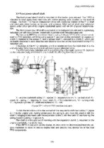
3.7 Front power takeoff shaft The front power takeoff shaft is mounted on the tractor upon request. The FPTO is intended to drive agricultural machines with active working units, located on the front lift linkage. The front PTO has an independent drive with clockwise rotation of the PTO shaft end extension when looked at its end, and provides 1000 rpm of shaft end extension speed under 2100 rpm of the engine crankshaft speed with 44 kW of power implementation. The front power take-off shaft is executed as an independent unit and is a planetary reduction unit with band brakes, mated with a parallel-shaft reduction gear unit. The torque to FPTO is transferred from a pulley 1 (figure 3.7.1) of the engine crankshaft to PTO reduction unit 9 through a spacer 2, secured on the crankshaft, an expansion clutch 3, installed in the spacer 2, and a splined shaft 4, secured in a clutch 5, which can be fixedly displaced in axial direction and which is mounted on the input shaft 8 of the PTO reduction unit. The power in the FPTO reduction unit 9 is transferred from the input shaft 8 to the end extension 12 by means of cylindrical meshing and planetary drive. The PTO planetary reduction unit 9 is controlled by a hydraulic cylinder 11, fastened on the reduction body and linked to a turn shaft 10, affecting band brake levers.

1 – engine crankshaft pulley; 2 – spacer; 3 – expansion clutch; 4 – splined shaft; 5 – clutch; 6 – spring; 7 – bushing; 8 – input shaft; 9 – PTO reduction unit; 10 – turning shaft; 11 – hydraulic cylinder; 12– shaft end extension; 13 – ball. Figure 3.7.1 – Front PTO (mechanical part) To link the reduction unit to the crankshaft it is required to shift the bushing 7 (figure 3.7.1) to the engine side, having compressed the spring 6, and move the clutch 5 with the shaft 4, bringing it into mesh with the expansion clutch 3 until the balls 13 are fixed by the spring-loaded bushing 7 in groove A. The shaft 4 is brought out of meshing with the expansion clutch 3, mounted on the engine crankshaft, in a similar way. If the FPTO is not used on the tractor, its drive shall be disconnected from the engine crankshaft in order to reduce engine load and ensure long service life of the front PTO components.

100


Turn static files into dynamic content formats.

Create a flipbook

Articles inside

10. TRACTOR DISPOSAL

1min
page 352

8.8 Safety requirements for preservation

1min
page 350

8.5 Preservation

2min
page 348

troubleshooting

4min
pages 344-346

washer, acoustic alarm

2min
page 336

7.15.3 Search and elimination of failures in engine start-up system

4min
pages 332-333

7.15.5 Search and elimination of failures in air conditioner electrics

3min
page 335

7.15.4 Search and elimination of failures in lighting facilities

3min
page 334

7.14.3 Section R-23LS lowering valve disassembly procedure

1min
page 329

troubleshooting

8min
pages 321-326

7.11 Possible failures of FDA and guidelines for troubleshooting

8min
pages 315-320

troubleshooting

1min
page 314

7.9 Possible failures in pneumatic system and guidelines for troubleshooting

3min
pages 312-313

7.8 Possible failures of brakes and guidelines for troubleshooting

5min
pages 309-311

7.7 Possible failures in front power take-off shaft and guidelines for troubleshooting

1min
page 308

troubleshooting

3min
pages 305-306

3.13 Undercarriage and tractor wheels

1min
page 129

3.12.3 Front PTO control

1min
page 128

3.12.2 FDA drive control

1min
page 127

3.11.4.2 Adjustment of FDA drive automatic switch

2min
page 125

3.11.3 Wheel gear group

2min
pages 122-123

3.9.5 Check and adjustment of pneumatic system pressure regulator

1min
page 118

system

1min
page 117

3.9.3 Double-line pneumatic drive of trailer brakes

2min
page 113

3.8.6 Parking brake

2min
page 110

3.8.7 Parking brake adjustment

1min
page 111

3.8.5 Service brake adjustment of “BELARUS-1822 .3/2022 .3”

1min
page 109

3.8.4 Service brake control of “BELARUS-1822 .3/2022 .3”

3min
pages 107-108

3.7 Front power takeoff shaft

3min
pages 101-102

3.8.3 Service brake adjustment of “BELARUS-1822.3/2022.3”

4min
pages 105-106

3.8.2 Service brake control of “BELARUS-1822.3/2022.3”

1min
page 104

3.6.2 Rear PTO control

2min
page 100

3.5.6 Rear axle final drive adjustment

2min
page 96

3.4 Reduction unit electro-hydraulic control

2min
pages 92-93

reduction unit

2min
page 90

3.3.3.5 Gearbox control

1min
page 91

3.1.4 Engine cooling system

1min
page 75

3.1.2 System of engine air cleaning

4min
pages 72-73

3.2.4.3 Clutch check for purity of disengagement

2min
page 82

3.1.3 System of charged air cooling

1min
page 74

3.3.3.3 Range shifting mechanism

1min
page 89

3.2.5 Clutch case

2min
page 83

3.1.1.2 Engine elements

8min
pages 68-71

2.24 Fuel tank valve control

1min
page 66

2.19.3 BELARUS seat installation for operation on reverse

1min
page 60

2.18.4 Cab hatch opening

1min
page 58

2.23 Reverse post controls of BELARUS-1822 .3/2022 .3

2min
pages 64-65

2.17.2 Fuses for electrical equipment system

3min
pages 53-55

2.17.3 Fuses of electronic control systems

1min
page 56

2.19.4 “Grammer” seat adjustments

1min
page 61
Issuu converts static files into: digital portfolios, online yearbooks, online catalogs, digital photo albums and more. Sign up and create your flipbook.
Belarus 1822.3 1822B.3 2022.3 2022B.3 Operator's Manual - PDF DOWNLOAD by www.heydownloads.com - Issuu