Linkbelt 210-240 X2 SERVICE MANUAL RST-00-00-001LX - PDF DOWNLOAD

Page 716

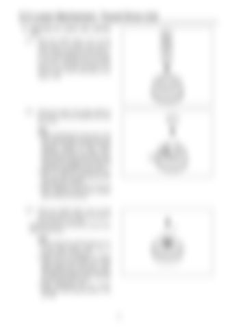
5-2 Lower Mechanism: Travel Drive Unit 6.) Assembling the cylinder block assembly (1-4) 6-1.)

Place the cylinder block (1-4-1) on the work bench of a manual press with its surface sliding against the valve plate (121) up. With the graded side of the collar (1-4-6) down, assemble it into the cylinder block (1-4-1), and place the spring (1-4-7) and the collar (1-4-8), in that order, on the collar (1-4-6).

6-2.)

Using a jig, press in the upper surface of the collar (1-4-8) and assemble the snap ring (1-4-5). Note: a.When assembling the snap ring (1-4-5) with snap ring pliers, the snap ring may drop out of the snap ring pliers due to its hardness, leading to injury. When assembling the snap ring, always use a jig and check that the claws of the snap ring pliers are engaged in the snap ring hole before proceeding with the work. b.When it is difficult to contract the snap ring, use snap ring pliers that are onesize larger than required. c.When pressing in the collar (1-4-8), be sure to align the center of the cylinder block with that of the press.

6-3.)

Place the cylinder block (1-4-1) on the work bench with its surface sliding against the valve plate (1-21) down. Assemble 3 pins (1-4-9) into the inclined holes of the cylinder block. Note: a.When placing the cylinder block (1-4-1) on the work bench, check that no foreign matter is present on it. b.Take care not to damage the sliding surface of the cylinder block (1-4-1) that slides against the valve plate (1-21). Damaging the sliding surface may affect the motor performance, which may lead to early failure of the motor. c.When assembling the pin (1-4-9), assemble it after applying grease in the pin halls.

113


Turn static files into dynamic content formats.

Create a flipbook

Articles inside

3.Upper Side Pilot Valve (remote control valve

5min
pages 787-791

2.5-way Solenoid Valve Operation Explanation

3min
pages 785-786

5.EPF (Engine Protection Feature

6min
pages 779-784

4.Sensor Trouble Operation Table

1min
pages 777-778

3.Diagnostic Trouble Code (Monitor display

3min
pages 772-776

1.Message Display List

2min
pages 766-767

9.Model Setting

2min
pages 763-764

10.Engine Screen Information Screen Display Details

1min
page 765

8.Anti-Theft Protection Setting

2min
page 762

7.Option Flow Setting

3min
pages 760-761

6.Check the Monitor Switch (monitor switch check screen

3min
pages 758-759

5.CAL (troubleshooting support) Screen

5min
pages 755-757

2.DIAG (trouble diagnosis) Screen

1min
pages 743-744

3.HR (usage log) Screen List

8min
pages 745-751

2.Swing Motor

1min
page 742

Screen Display List 1.CHK (status display) Screen List

11min
pages 732-741

1.Screen Shift

1min
page 731

5.Beacon

4min
pages 728-730

1.Travel Motor

1min
page 723

4.Return Filter Restriction Detected

1min
page 727

2.Regulator

2min
pages 716-718

Options 1.Option Line Control

3min
pages 719-721

1.Hydraulic Pump

2min
pages 714-715

1) Breaker Q control

1min
pages 708-709

2) 2nd crusher

1min
pages 710-711

1.Breaker Circuit (single operation

3min
pages 704-705

4.Second Option Circuit (hydraulic rotation fork

1min
pages 712-713

2.Shuttle Circuit (hydraulic thumb

2min
pages 706-707

2.Heat Circuit (lever in neutral

2min
pages 700-701

2) When arm-out operation stopped

1min
pages 696-697

Retightening torque table

18min
pages 664-689

ISO type

1min
page 656

Increased Horsepower Circuits 1.Arm-In Increased Horsepower Circuit

1min
pages 690-691

7.Pressure Limiter

1min
page 636

1) Arm-out operation

1min
pages 694-695

2.Travel Increased Horsepower Circuit Other Circuits

2min
pages 692-693

Maintenance after first 250 hours for new machine / every 1000 hours from then ON 1.Swing Reduction Gear Oil Replacement

1min
page 660
Issuu converts static files into: digital portfolios, online yearbooks, online catalogs, digital photo albums and more. Sign up and create your flipbook.