5 minute read
3.Upper Side Pilot Valve (remote control valve


2. Crossover relief valve
The purpose of this valve is to determine the motor drive force and braking force. Therefore, this valve has a shockless function to soften the shock when the motor starts and stops and provide good operability.
Also, this valve is formed into one compact unit with the double counter balance valve to make up the brake circuit.
Important
This relief valve is not designed for hydraulic circuit protection. Install another relief valve to protect the hydraulic circuits.
3. 2nd-speed switching mechanism
This motor has a 2nd-speed switching mechanism that can switch the motor speed between 2 speeds, low speed and high speed. Automatic 2nd-speed function is also available as an option.
Supplement
About automatic 2nd-speed function The low-speed mode fixed position and automatic 2nd-speed position can be selected. When the automatic 2nd-speed position is selected, the motor capacity is selected according to the motor load pressure and the motor is switched automatically between low speed and high speed.
4. Parking brake
The parking brake function is built into the piston motor. When the motor is stopped, the mechanical brake operates to prevent the motor from being rotated by external load.
Important
This brake is not intended to apply braking force when the motor is running. Use of this brake for braking will accelerate disk wear, causing poor braking performance or damage to the shaft. Never use this brake for braking the running motor.
5. Piston motor
A swash plate-type piston motor is used. This piston motor converts the fluid energy of the pressurized oil sent from the hydraulic pump into mechanical energy and outputs high-speed, low-torque power.
6. Reduction gear
A simple planetary 2-stage reduction gear structure of the casing rotation type is used. This reduction gear converts the high-speed, low-torque power output from the piston motor into low-speed, high-torque power and outputs it from the reduction gear casing.
Also, a floating seal is used to prevent mud, sand, water, etc. from infiltrating from the outside.
The component devices above are formed into one compact unit that provides high reliability and superior performance.
7.Component Configuration and Operation
[1]Component configuration
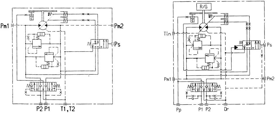
Figure 3 shows a structural diagram of the motor, and Figure 4 shows a hydraulic circuit diagram of the motor.
This motor integrates the various components described in Section 5 in a compact unit. See Figure 3 and 4 for each component part.
Figure 3. Motor structural diagram
Manual 2nd-speed type
Figure 4. Hydraulic circuit diagram
Automatic 2nd-speed type
[2]Operation explanation of each component 1. Double counter balance valve
The double counter balance valve serves the following functions. 1. The overrun prevention function that controls the piston motor speed to match the feed quantity when an external load is applied and that drives the motor higher speed than that is determined by the flow feed (below, pumping action). 2. The brake function used together with the crossover relief valve to make up the brake circuit that gradually stops the rotation of the piston motor by applying braking force to the piston motor rotation. 3. The high-pressure selection shuttle valve function for releasing the parking brake through its own pressure.
Figure 5 shows a structural diagram of the standard double counter balance valve. This section explains the operations of each function using this standard double counter balance valve.
Oil path C1
Orifice D1
Damper chamber A1
Orifice D2
Spring chamber 1 Oil path B
Oil path C2
Orifice D3
Damper chamber A2
Orifice D4
Spring chamber 2
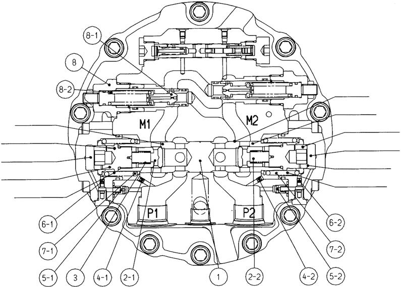
Figure 5. Double counter balance valve structural diagram (stopped state)
A. Stopped state (Figure 5)
When the control valve is in neutral (the motor stopped), since pressure is generated at neither the P1 port nor the P2 port, the M1 and M2 ports are locked (hydraulically) with the spool (1) and the check valve (2) and the piston motor does not rotate.
B. When motor starts (Figure 6)
When the pressurized oil discharged from the hydraulic pump is led to the double counter balance valve
P1 port, the check valve (2-1) moves to the left against the spring (3), the oil path C1 is opened. And the pressurized oil flows from the M1 port into the piston motor and attempts to rotate the piston motor.
On the other hand, the return oil from the piston motor flows from the M2 port into the double counter balance valve, but the flow is prevented by the check valve (2-2) and the hydraulic pump discharge pressure rises.
Therefore, the P1 port side goes to high pressure, the pressurized oil operates through the orifice (4-1) and the check valve (5-1) on the spring chamber 1 and the damper chamber A1, and that oil pressure moves the plunger (1) to the right against the opposite side spring (7-2) with force proportional to the pressure.
At this time, the M2 port return oil flows through the oil path B in the circumferential notch section of the plunger (1) and into the P2 port while generating back pressure at the M2 port. This return oil returns to the tank through the control valve and the piston motor starts rotating.
C.Counter balance function (Figure 6)
During piston motor rotation, if the piston motor is forced to rotate by the external load, a pumping action occurs in the piston motor, and the motor may go out of control. In this case, since the P1 port section becomes the suction side of the pump action, that pressure drops. At the same time, the pressure also drops in the spring chamber 1 and the damper chamber A1. Therefore, the plunger (1) is moved to the left by the spring (7-2), oil path B is closed, and when the return oil flow stops, the suction side flow stops at the same time.
When the flow of oil through oil path B is stopped, in an instant, the P1 port side pressure rises again due to the hydraulic pump discharge oil and this moves the plunger (1) to the right.
In this way, the plunger (1) moves in small steps when there is pumping action due to the external load to hold the opening surface area of oil path B in an appropriate state. Therefore, rotation of the piston motor at a speed appropriate to the feed flow from the hydraulic pump is maintained and vacuum in the hydraulic circuit is prevented. This prevents the piston motor from going out of control.