11 minute read
Screen Display List 1.CHK (status display) Screen List


[2]Types of reduction gear lubricating oil and selecting appropriate one
Table 8 shows the API Service Categories for reduction gear lubricating oil.
Table 8. API Service Categories for Reduction Gear Lubricating Oil
Use reduction gear lubricating oil equivalent to "GL-4 or GL-5".
Service Categories Type of Service Applications
GL-1 Spiral bevels or worm gears with small surface pressure and sliding velocity Used for manual transmission on rare occasions and rarely used today.
GL-2 Slightly more demanding worm gears than above mentioned. Used for industrial worm reducers.
GL-3 Slightly more demanding spiral bevels and manual transmission Mainly used for manual transmission.
GL-4
GL-5 Hypoid gears under highspeed and low-load or low-speed and high-load
Much more demanding hypoid gear to which shock load is applied Hypoid gear reducer under normal conditions. Also used for manual transmission. Passenger cars, racing cars, and the track rear axle of the hypoid unit that have high requisite.
[3]Reduction gear lubricating oil appropriate for the operating temperature
Table 9 shows JIS viscosity grades for reduction gear lubricating oil.
Table 9. JIS viscosity Grades for Reduction Gear Lubricating Oil
Higher viscosity provides more load bearing but may cause a problem with the starting performance if the viscosity is too high. Therefore, selecting reduction gear lubricating oil appropriate for the operating temperature is necessary.
Type (Viscosity grade) Kinematic Viscosity cSt (100°C)
SAE 75W 4.1 or higher
SAE 80W
7.0 or higher SAE 85W 11.0 or higher SAE 90 13.5 or higher and less than 24.0 SAE 140 24.0 or higher and less than 41.0
Table 10 shows selection criteria for the viscosity of the reduction gear lubricating oil for various operating temperatures. Select the viscosity of the reduction gear lubricating oil by following this table. Note that a given amount of diamond hypoid gear oil 90 from Mitsubishi Oil has been fed by the factory setting.
Table 10. Selection Criteria for the Viscosity of the Reduction Gear Lubricating Oil for Various Operating Temperatures
Operating
Temperature Extremely Hot Area Summer Spring, Fall, Winter Extremely Cold Area
Viscosity grade SAE140 SAE90 or SAE140 SAE90 SAE80W
Important
Do not mix different types of reduction gear lubricating oil when replacing the lubricating oil.
9.Storing the Motor
[1]Immediately after purchase
The guaranteed storage period of the swash plate-type piston motor with case rotation type reduction gear for the open circuit is one year after shipment form the factory.Do not store the motor for longer than this period. In addition, do not disassemble the motor during the storage period or loosen the bolts.
How to store the motor
Some hydraulic oil is applied on the inside of the equipment because it is tested before the shipment. In addition, antirust agent is applied on each port section, the installation face of the mother machine, and the mounting tap section. Do not wipe off the antirust agent. Storage period should be within three months. If longer storage is expected, please contact us in advance because the way to prevent rust is different.
For shipment, the product is covered with a plastic bag that prevents dust from entering. Do not remove the plastic bag when storing the product.
Store the product in an indoor area to protect it from rainwater etc. Avoid a place subject to high temperature and humidity. Store the product at ordinary temperature and humidity.
The product is shipped with the dedicated palette. Leave the packaging as it is not to damage the motor and store it in a stable place.
[2]Management method after maintenance check
When storing the motor after a maintenance check, follow the instructions below.
In this case, please be reminded that you are responsible for any problem (for example, scratches and rust) that occurs on the motor.
How to store the motor
When storing the motor after a maintenance check, make sure that fastening bolts of all sections are fastened to a given tightening torque and that air is not leaking from any sealed section, and then start and stop the motor before storing. (For the procedure to run the motor, see the operating method described elsewhere. ) If it is impossible to run the motor, feed about 500 cc of hydraulic oil into the piston motor case and about 3.5 L of reduction gear lubricating oil into the reduction gear before storing.
Before storing, spray vaporizing antirust oil on the insides of the piston motor case, the piston motor circuit, and the reduction gear from the ports of the motor and then seal all the port sections with plugs by following the instructions below.
Apply antirust agent on the non-coated areas on the installation faces, screw sections, and port sections, etc.
To prevent dust from entering, cover the product with a plastic bag and then store it. Store the product in a stable place, placing the reduction gear side down. Store the product in an indoor area to protect it from rainwater etc. Avoid a place subject to high temperature and humidity. Store the product at ordinary temperature and humidity.
Instructions for preventing rust
1. Preventing rust on the non-coated exterior areas
To prevent rust on the non-coated exterior areas, apply antirust agent on them following the instructions below. (1)Areas that need antirust treatment The installation surface to the mother machine, the threaded section for connection, and the noncoated areas of the pipe port section or other sections (2)Applying method Apply agent once with a brush. (3)Recommended antirust agent Brand:NOX-RUST 366-30 Manufacturer: Parker Industries, Inc. 2. Preventing rust on the interior areas of the piston motor and the reduction gear
To prevent rust on the interior areas, spray vaporizing antirust oil on them following the instructions below. (1)Areas that need antirust treatment The oil paths in the piston motor including valves, the inside of the piston motor case, and the inside of the reduction gear (2)Spots to be sprayed The oil paths in the piston motor including valves: Main port (P1, 2) The inside of the piston motor case: Oil drain port (T) The inside of the reduction gear: Either the reduction gear lubricating oil feed/drain or the level port (3)Amount to be sprayed The oil paths in the piston motor including valves: 2 cc The inside of the piston motor case: 4 cc The inside of the reduction gear: 4 cc (4)Recommended vaporizing antirust oil Brand: APORRY VC200 Manufacturer: SAN-AI OIL Co., Ltd.
10.Names for Motor Sections
Reduction gear lubricating oil Oil fill port Reduction gear lubricating oil Oil check port Reduction gear lubricating oil Oil drain port
Connecting to driven section of machine main unit installation surface Output rotation section
Connecting surface to driven section of Main pipe port P1
machine main unit installation tap Drain pipe port Dr Connecting to machine main unit frame installation surface
Main pipe port P2 Connecting surface to machine main unit frame installation tap
Oil fill port (In the motor case) Tin Pressure detection port Pm1
2nd-speed pilot pipe port Ps Pressure detection port Pm2 Parking brake release port (external) Po
11.Motor Installation
[1]Motor inspection
Before installing the motor on the mother machine, check the following items and apply the indicated solutions if there is any problem.
Table 11. Motor Inspection before Installation and Solutions for Problems
Items to be Checked before Installation Solutions for Problems When installing the motor after purchase When installing the motor that has been stored after a maintenance check
Are there any damaged parts?
Are there any missing parts? For parts damage during shipping, contact the following address. For parts damage during storage, replace the damaged parts with new ones. For parts missing during shipping, contact the following address. For parts missing during storage, purchase new ones.
Have any bolt tightening sections not been loosened?
If any bolt has been loosened immediately after purchase, contact the following address and then retighten it to the specified torque. If any bolt has been loosened after storage, there may be rust on the inside. Contact the following address. Dirt on the ports If any pipe port is dirty, clean it by blowing it with compressed air, a high pressure jet, or vapor to remove the dirt.
Are all port sections completely sealed? Immediately after purchase: If any port plug has been loosened, remove dirt on the port before starting to use. If there is a port that does not have a plug, dirt may have entered inside. Contact the following address. Replace the damaged parts with new ones.
Purchase new ones.
If any bolt has been loosened, disassemble the motor again to check for rust on the inside.
If any pipe port is dirty, clean it by blowing it clean it by means of air blow with compressed air, a high pressure jet, or vapor to remove the dirt. If any port plug has been loosened or if there is a port that does not have a plug, disassemble the motor to check inside for dirt and rust.
Is there any rust on the port sections and the installation surface to the mother machine? Oil leaking from the port sections and the joint surface After storage: There may be rust on the inside. Contact the following address. If there is any rust, contact the following address.
If there is oil leaking, contact the following address. If there is a small amount of rust, remove the rust and use the motor. If there is a large amount of rust, replace the parts. If there is oil leaking, there may be a problem relating to the sealing performance and rust may have occurred inside. Disassemble the motor again to check inside for rust.
[2]Selecting pipes 1. Pipe size
When selecting pipes, check and determine the type of the hydraulic oil, temperature, maximum pressure, whether surge pressure is produced or not, maximum flow, and piping length to achieve full hydraulic circuit functions.
Use steel pipes for pressure piping and precision steel pipes for hydraulic piping. If equipment that involves position changes is included, use rubber hoses.
Select pipe size based on Table 12 "Required Pipe Size" and Table 13 "Required Flow Velocity in the Pipe".
Table 12. Required Pipe Size
Do not use a pipe smaller than the size shown in the table. Otherwise, abnormally high pressure or other problems may occur.
Table 13. Required Flow Velocity in the Pipe
In particular, when the piping length is large and the temperature of the hydraulic oil is low, pressure loss by flow will be large. In that case, a problem may have been caused. Choose larger pipes and reduce the flow velocity to minimize pressure loss. For a drain pipe, select pipe size with which drain pressure in the motor oil drain port section does not exceed the tolerance range shown in Table 14. For the low pressure return piping, select pipe size with which back pressure in the motor outflow port (P1 or P2) section will be equal or less than 2.0 MPa.
Table 14. Drain Pressure Tolerance Range
Pipe Port Name Pipe Size
Inflow port (P1 or P2) Outflow port (P1 or P2) Oil drain port (T1 or T2) 1" or higher
1" or higher
1/2" or higher
2nd-speed switching pilot port (Ps) 1/4" or higher
Position in a Pipe Required Flow Velocity (m/s) High pressure circuit 5.0 m/s Low pressure return circuit 1.5 m/s Pump suction circuit 1.0 m/s
Drain Pressure Tolerance Range Normal use 0.2 MPa max. Instant maximum 0.5 MPa max.
2. Pipe wall thickness
It is important that the pipes can bear the maximum operating pressure including surge pressure. Therefore, select pipe wall thickness that complies with safety ratio 5 or higher for maximum pressure in the system including surge pressure. If your ship or other vessel specifies different safety factor, observe it.
[3]Motor transport
When transporting the motor, always use a crane or carrier.
Motor weight: About 290 kg
Important
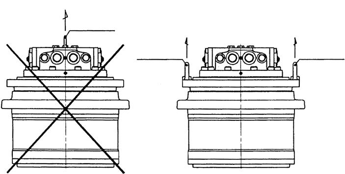
• Lifting the motor by the hands may cause damage to your back or injury. • When lifting the motor with a crane, use the eye bolts and the fixing taps on the fixed side frame installation surface of the machine main unit of the motor as shown in Figure 23.
Should not be lifted up
Eye bolt lift up
Eye bolt lift up
Eye bolt
Figure 23. Hanging up the motor with a crane
[4]Installation to the machine main unit
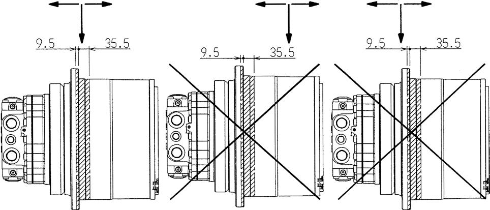
When installing the motor to the machine main unit, make sure that the pipe ports of the motor are in the correct orientation as shown Figure 24. Do not install the motor vertically to the ground.
Machine main unit fixed side frame
Machine main unit driven side frame
Top Top
Bottom
Top Top
Machine main unit driven side frame
Bottom Machine main unit fixed side frame
Section B
Bottom
Machine main unit fixed side frame Machine main unit driven side frame
Section B, machine main unit fixed side frame Bottom Machine main unit fixed side frame
Top Machine main unit driven side frame
The machine main unit fixed side frame should be chamfered by C3 or more. Down Machine main unit fixed side frame Machine main unit driven side frame
Figure 24. Installation to the machine main unit and the orientation of the motor pipe ports.
To install the motor to the machine main unit, mount the main unit frame on the fixed side installation surface and fasten the frame and the motor with bolts. Use a tightening torque that complies with the specifications defined by the manufacturer of the machine main unit.
[5]Driven section installation
This motor employs a direct drive system where the motor drives the driven section directly. Therefore, the driven section should be directly mounted on the rotation side installation surface and tightened with bolts. Use a tightening torque that complies with the specifications defined by the manufacturer of the machine main unit.
Important
Keep in mind the following guidelines when installing the driven section:
I. The eccentric amount between the motor rotation section and the driven shaft should be 0.1 mm (FIR) or less. II. An external force working on the motor should not exceed the value shown in Table 2. III.The working position of an external load on the motor should not exceed the range shown in Table 19.
Thrust load Thrust load
Radial load Thrust load Thrust load
Radial load Thrust load
Radial load