1 minute read
2.DIAG (trouble diagnosis) Screen


[6]Pipe installation 1. Piping and the motor rotation direction
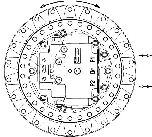
Before performing piping, make sure the motor rotation direction determined by the combination of the inflow port and the outflow port for hydraulic oil. Table 15 and Figure 26 show the motor rotation direction determined by the combination of the inflow port and the outflow port for hydraulic oil.
Table 15. Motor Rotation Direction Determined by the Combination of the Inflow Port and the Outflow Port for Hydraulic Oil
Hydraulic Oil Inflow Port Hydraulic Oil Outflow Port Motor Rotation Direction (Rotation direction viewed from ) P1 port P2 port C direction (clockwise direction) P2 port P1 port A direction (anticlockwise direction)
Important
If the pipes are incorrectly installed, the motor will rotate in the unintended, opposite direction, creating a highly dangerous situation. Make sure to check the pipe port positions and the motor rotation direction before carrying out piping.
A direction (anticlockwise direction) rotation C direction (clockwise direction) rotation
Figure 26. Motor rotation direction determined by the combination of the inflow port and the outflow port for hydraulic oil
2. Positional relationship between the motor and the hydraulic tank
On valves such as the piston motor valves and the double counter balance valve, there are slight leaks from their slits. Therefore, leaving the motor stopped for a long period of time may cause the hydraulic oil to leak from and air to accumulate in the motor circuit or the hydraulic circuit. Air in the circuit may cause a malfunction such as runaway phenomena upon starting of the motor after a long period of neglect. To prevent such an accident, place the hydraulic tank above the hydraulic motor in order for the hydraulic oil not to leak from the circuit.
Important
If the hydraulic tank needs to be placed below the motor due to space or other limitations, make sure to set up a self-supply circuit and fill it with hydraulic oil before running the motor.
Hydraulic tank
Hydraulic tank
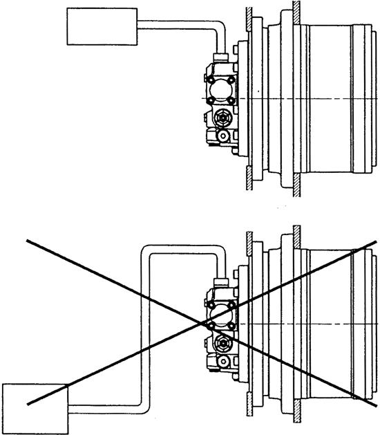
Figure 27. Positional relationship between the motor and the hydraulic tank