Linkbelt 210-240 X2 SERVICE MANUAL RST-00-00-001LX - PDF DOWNLOAD

Page 706

5-2 Lower Mechanism: Travel Drive Unit 4.) Assembling the housing (4) onto the flange (1-1) Check the following points. Then assemble housing (4) onto the flange (1-1) so that floating seal (2) on the flange (1-1) falls on floating seal (2) on the housing (4).

the the the the

Confirmation: a.Check that the sliding surface of the seal ring of the floating seal (2) is free from soil or dust. b.Apply lubricating oil for the reduction gear or hydraulic oil all around the sliding surface of the seal ring of the floating seal (1-2). c.When assembling the flange holder (1-1) on the housing (1-6), check that the shaft centers are aligned, and then proceed with the assembly.

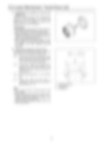
Using a shim thickness adjusting jig, apply load of 3000 kgf on the end surface of the inner race of the angular bearing (3).

5-2.)

In this step, measure step dimension H between the inner race surface in the angular bearing (3) and the end surface of the flange (1-1).

5-3.)

Measure step dimension “h” for the holder (6).

5-4.)

Select the shim (5) and form a combination so that the shim thickness is appropriate for (H - h).

*1

*2

5-1.)

*3

5.) Selecting the thickness of the shim (5) According to the following procedure, select the shim thickness for pre-pressure adjustment.

*1 *2 *3

Note: a.Do not use the shim (5) that has been used once already. b.Perform this procedure securely. Failure of prepressure adjustment leads to breakage of the reduction gear during operation. c.Clean the surface subject to measurement and start measurement.

103

Press load 300 kgf Dimension H Dimension h


Turn static files into dynamic content formats.

Create a flipbook

Articles inside

3.Upper Side Pilot Valve (remote control valve

5min
pages 787-791

2.5-way Solenoid Valve Operation Explanation

3min
pages 785-786

5.EPF (Engine Protection Feature

6min
pages 779-784

4.Sensor Trouble Operation Table

1min
pages 777-778

3.Diagnostic Trouble Code (Monitor display

3min
pages 772-776

1.Message Display List

2min
pages 766-767

9.Model Setting

2min
pages 763-764

10.Engine Screen Information Screen Display Details

1min
page 765

8.Anti-Theft Protection Setting

2min
page 762

7.Option Flow Setting

3min
pages 760-761

6.Check the Monitor Switch (monitor switch check screen

3min
pages 758-759

5.CAL (troubleshooting support) Screen

5min
pages 755-757

2.DIAG (trouble diagnosis) Screen

1min
pages 743-744

3.HR (usage log) Screen List

8min
pages 745-751

2.Swing Motor

1min
page 742

Screen Display List 1.CHK (status display) Screen List

11min
pages 732-741

1.Screen Shift

1min
page 731

5.Beacon

4min
pages 728-730

1.Travel Motor

1min
page 723

4.Return Filter Restriction Detected

1min
page 727

2.Regulator

2min
pages 716-718

Options 1.Option Line Control

3min
pages 719-721

1.Hydraulic Pump

2min
pages 714-715

1) Breaker Q control

1min
pages 708-709

2) 2nd crusher

1min
pages 710-711

1.Breaker Circuit (single operation

3min
pages 704-705

4.Second Option Circuit (hydraulic rotation fork

1min
pages 712-713

2.Shuttle Circuit (hydraulic thumb

2min
pages 706-707

2.Heat Circuit (lever in neutral

2min
pages 700-701

2) When arm-out operation stopped

1min
pages 696-697

Retightening torque table

18min
pages 664-689

ISO type

1min
page 656

Increased Horsepower Circuits 1.Arm-In Increased Horsepower Circuit

1min
pages 690-691

7.Pressure Limiter

1min
page 636

1) Arm-out operation

1min
pages 694-695

2.Travel Increased Horsepower Circuit Other Circuits

2min
pages 692-693

Maintenance after first 250 hours for new machine / every 1000 hours from then ON 1.Swing Reduction Gear Oil Replacement

1min
page 660
Issuu converts static files into: digital portfolios, online yearbooks, online catalogs, digital photo albums and more. Sign up and create your flipbook.