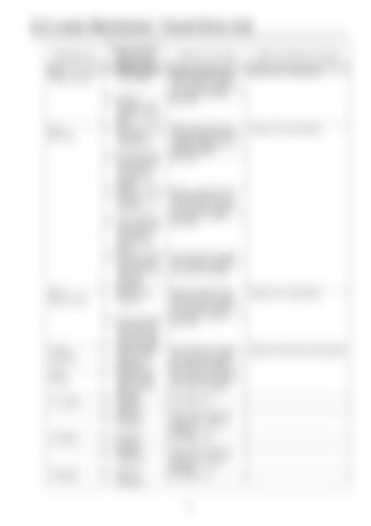
5-2 Lower Mechanism: Travel Drive Unit Applicable Part 1-2-2 Plunger assembly
1-2-1 Base plate
Sections subject to Inspection and Measurement 1. External diameter of the plunger
2. External diameters of the plunger and base plate 1. Hole for mounting the plunger assembly (2-2) 2. Internal diameter of the base plate and external diameter of the plunger 3. Hole for mounting the spool assembly (2-11)
1-2-9 Spool assembly
1-2-7-9 Free piston 1-2-7-1 Housing
1-4-7 spring
1-18 spring
1-20 spring
4. Internal diameter of the base plate and external diameter of the spool 5. Free piston sliding section and the seat section of the relief valve assembly 1. External spool diameter
2. External diameter of the spool and internal diameter of the base plate 1. Sliding and seat sections of the base plate 1. Sliding section against the free piston (external diameter) 1. External dimensions 2. External dimensions 1. External dimensions 2. External dimensions 1. External dimensions
Tolerance Limit Value
Repair and Solution Procedure
Relative roughness 0.8 a The surface has a scratch 0.02 mm deep or deeper, or the surface is chapped. Gap 0.060
Replace with a base plate kit
Relative roughness 0.8 a The surface has a scratch 0.02 mm deep or deeper, or the surface is chapped. Gap 0.060
Replace with a base plate kit
Relative roughness 0.8 a The surface has a scratch 0.02 mm deep or deeper, or the surface is chapped. Gap 0.060
The surface has a scratch 0.02 mm deep or deeper, or the surface is chapped.
Relative roughness 0.8 a The surface has a scratch 0.02 mm deep or deeper, or the surface is chapped. Gap 0.060
Replace with a base plate kit
The surface has a scratch 0.02 mm deep or deeper, or the surface is chapped. The surface has a scratch 0.02 mm deep or deeper, or the surface is chapped.
Replace with the relief valve assembly.
Free length: 61.0 Deformation is observed, and the coil surface is damaged. Free length: 39.0 Deformation is observed, and the coil surface is damaged. Free length: 41.5
97


