VIII. SERVICE AND MAINTENANCE
.375” shim
TREAD ADJUST SHIM ADJUSTMENT
.250” shim
NOTE: If the leg mount bolts have been tightened to the
.074” shim
proper torque and the mount is loose, it may be that the bearing has worn and needs to be replaced.
.025” shim
Check the bearing before you remove shims.
.037” shim When adjusting for more or less bearing clearance, park the nylon bearings
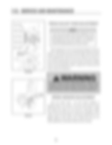
sprayer on level ground and shut off the engine. Block the wheel of the opposite side, both front and rear. Remove only three of the six leg mounting bolts at one time when removing or adding shims to the leg assembly. Refer to page 95 for leg mount bolt torque values and sequence. FIG 8.50
DO NOT loosen the leg mounting bolts to obtain more clearance for the leg to slide on the frame. Follow the above directions only for bearing clearance adjustment. speed sensor
SPEED SENSOR ADJUSTMENT (Left rear wheel motor - fig. 8.51) When installing or adjusting sensor, turn sensor in by hand until contact is made with speed ring. Back out one half turn (.030 gap). Rotate sensor until the wrench flats on housing are positioned at a 22
FIG 8.51
degree angle to motor shaft. Lock in place with lock nut. For further adjustment, see Sauer-Danfoss service manual.


