1 minute read
V. OPERATING INFORMATION


Electric Solution Valves
The spray booms are divided into sections that are independently supplied with solution and can therefore independently be shut off or turned on. The number and location of solution valves varies with boom length. Sixty foot booms are divided into three sections and the valves are mounted on the transom. Eighty and ninety foot booms are divided into five sections with three valves mounted on the transom and one mounted on each boom.
Boom Valve Switches
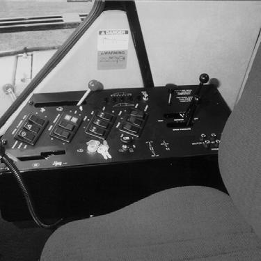
The electronic boom solution valves are controlled by a panel of switches mounted under the spraying system’s monitor (fig. 5.28). When the switches are in the “UP” position they are on and when they are in the “DOWN” position they are off.
Main Solution Switch
The main solution switch is a floor-mounted “dimmer-style” switch (fig. 5.29, item 2). It controls the power supply to the panel of boom solution valve switches. The main floor switch must be on to supply the panel switches with voltage. This way you can turn all of the boom solution valves “ON” or “OFF” all at once in a hands-free execution such as turning the main solution switch “OFF” as you arrive at the end rows of a field and turn it back “ON” as you enter the field again.
When the main solution switch is “ON” a “GREEN” indicator light mounted at the bottom of the instrument panel will light up (fig. 5.29, item 1). When the light is not lit, the main solution switch is “OFF.”