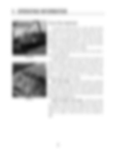
V. OPERATING INFORMATION Fence Row Applicator To operate the optional fence row nozzle, locate the fence row switch at the front of the switch control panel (fig. 5.30). If you wish to turn on either the right or left fence row nozzle, depress the corresponding “RIGHT” or “LEFT” side of the fence row switch. To turn either fence row nozzle off, return the fence row switch back to the center (“OFF”) position. As you engage either fence row nozzle you may notice a drop in solution pressure. FIG 5.30 A lighted indicator mounted next to the fence row switch will inform the operator of fence row status. If the right fence row nozzle is on, the right indicator arrow is lit (fig. 5.31, item 2). If the left fence row nozzle is on, the left indicator arrow is lit (fig. 5.31, 2
item 1). If neither indicator arrow is lit, no solution is being applied through the fence row nozzles. SIXTY FOOT BOOM – The fence row nozzle on a sixty foot boom is supplied by an electric valve mounted in-line with the left or right boom solution supply hose. In order to operate the fence
1
row nozzle on a sixty foot boom, the corresponding boom section (left or right) must already be on. FIG 5.31 EIGHTY OR NINETY FOOT BOOM – The fence row nozzle on an eighty or ninety foot boom is supplied by an electric valve attached to the outer boom electric solution valve. The fence row nozzle on an eighty or ninety foot boom may be operated by itself.


