V. OPERATING INFORMATION HYDROSTATIC SYSTEM CONTINUED
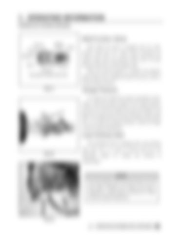
Multi-Function Valves Each Series 90 pump is equipped with two multifunction valves (fig. 5.7). These valves incorporate the system check valve, the pressure limiter valve, the high pressure relief valve, and the bypass valve. When the pre-set pressure is reached, the pressure limiter system acts to rapidly de-stroke the pump in order to limit the system pressure. FIG 5.7
Charge Pressure To monitor the closed loop system (hydrostatic pump), install a 500 PSI pressure gauge at the charge pressure port (fig. 5.8). Start the engine and open the throttle to full RPM. The charge pressure should be between 348 and 365 PSI. If it is below the required pressure, contact the Hagie Customer Support Department.
Loop Flushing Valve The hydrostatic pump is equipped with a loop flushing valve (fig. 5.9). It is used to remove fluid from the FIG 5.8
hydrostatic
system
for
cooling
and
removal
contamination.
NOTE: The loop flushing valve has been factory set. DO NOT adjust. Damage to the system may result if adjustment is made without contacting the Hagie Customer Support Department.
FIG 5.9 OPERATING INFORMATION CONTINUED
of


