1 minute read
V. OPERATING INFORMATION


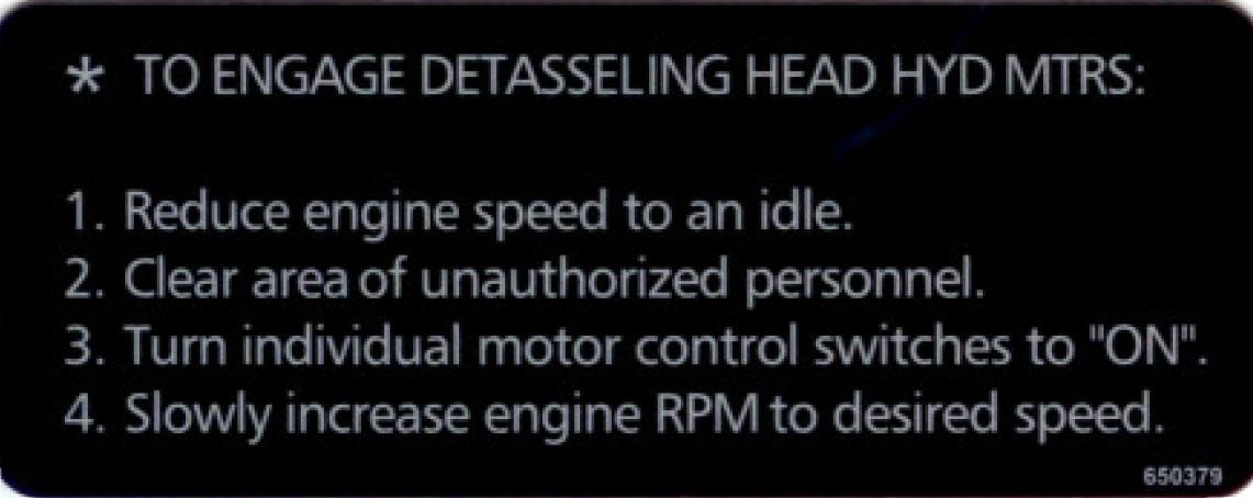
This valve is preset at the factory and requires no adjustment. Activate hydraulic motors while engine speed is at an idle, then increase engine RPM to operating speed.
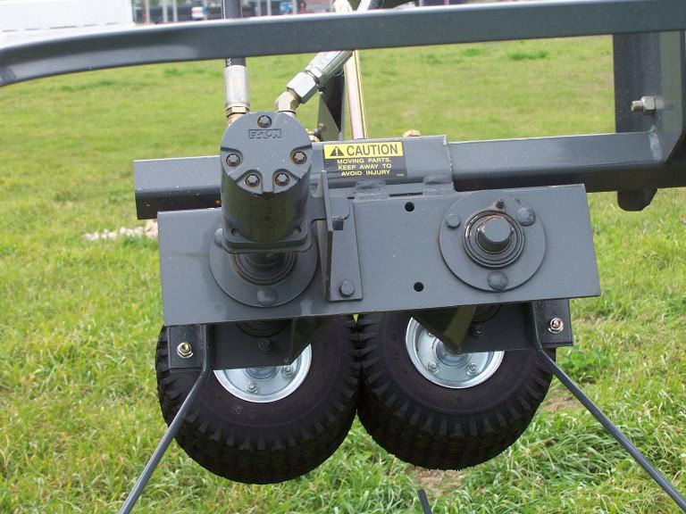
Detasseling Heads

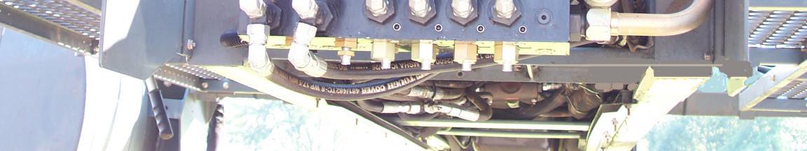
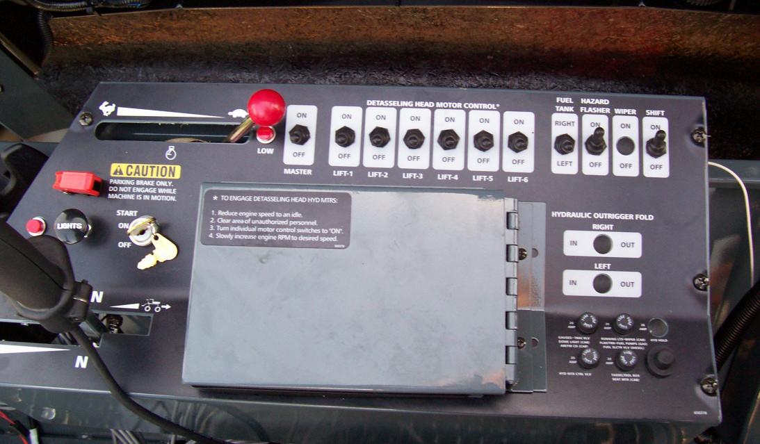
The hydraulic motors on the detasseling heads (fig. 5.30) are controlled by the master switch (fig. 5.29, item 1) and individually (per lifts) turned on and off with a row o f switches mounted on the control panel to the right of the op erator’s seat (fig. 5.29, item 2). To open the solenoid of any of the motor control valves (fig. 5.28) which activate the hydraulic motors, flip the corresponding switch(es) away from the operator. To shut any or all motors off, flip the corresponding switch(es) toward the operator.
Each set of motors are controlled with an adjustable needle valve (fig. 5.28, item 1) that restricts hydraulic flow to the hydraulic motors so they don’t over-speed and become damaged.