VII. SERVICE AND MAINTENANCE ELECTRICAL CONTINUED
Circuit Breakers Circuit breakers handle the functions of the
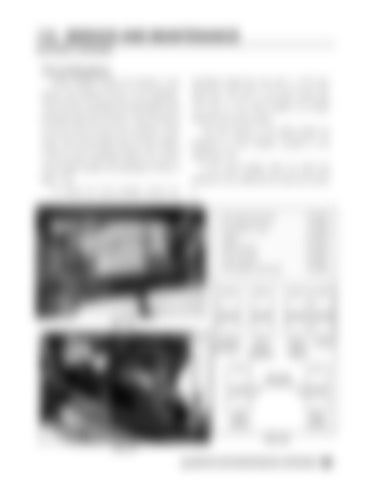
hydrostatic handle (fig 7.46, item 1), VFC lever
heavier duty electrical circuits on the detasseler.
knobs (fig. 7.46, item 2), and panel screws (fig.
They trip when overloaded and automatically reset
7.46, item 3). The circuit breakers are located
themselves after they cool down. They will continue
toward the rear of the console.
to trip and reset as long as the overload or short
The wire harness on the diesel engine are
exists. If the circuit breaker does not reset, replace
protected by circuit breakers mounted on the
it with the same amperage breaker only. Correct
engine (fig. 7.47).
circuit breaker location and amperage is shown in figure 7.48.
continues to trip, determine the cause and correct
To access the circuit breakers remove the
3
If the circuit breaker does not reset and
it.
A/C relay (cab only)…………….30 AMP
2
Fuel Injector relay ……….………40 AMP 3
Lights……………………...……..40 AMP Wire harness…………………….30 AMP
1
Wire harness …………………...50 AMP A/C breaker (cab only)………….30 AMP
30 AMP BREAKER
30 AMP BREAKER
40 AMP BREAKER
40 AMP BREAKER
A/C RELAY (CAB ONLY)
A/C BREAKER (CAB ONLY)
FUEL INJECTOR RELAY
LIGHTS
FIG 7.46
MOUNTED ON ENGINE 30 AMP BREAKER
50 AMP BREAKER
WIRE HARNESS
WIRE HARNESS
FIG 7.48 FIG 7.47 SERVICE AND MAINTENANCE CONTINUED


