Disassembly of AML Main Unit 3. Removing CPU Board/Analog Board /Power Board
3.1 Notes on ROM/EEPROM Replacement [NOTICE] EEPROM stores the adjustment values for each specification number. When replacing the CPU board, remove the EEPROM from the broken CPU board and reuse it.
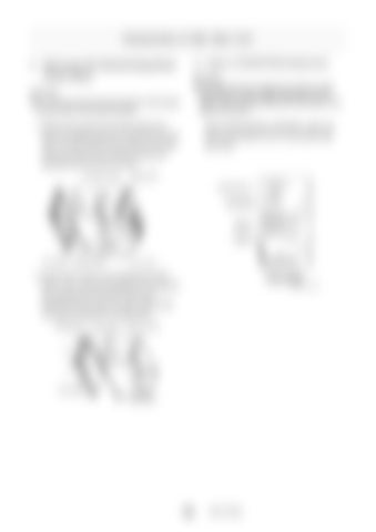
[NOTICE] Do not touch each front and rear face of the boards by hand when removing the boards. 1. Remove the screws (a) and take off the front
When replacing ROM or EEPROM, make sure that the concavities of the IC and socket meet each other.
panel and display board as an assembly from the main unit case. Remove the screws (c) and take off the rear panel and connector board as an assembly from the main unit case. コネクタ基板 Connector board
c
Rear panel 後面パネル Calendar/clock カレンダ/時計
電池 Batteries CN1
EEPROM CN4 PLD
ROM 1 CPU
ROM 0
CN2
a
Main unit case 本体ケース 表示基板 前面パネル Front panel Display board IW301-0252J09
CN3
2. Remove the screws (f) and separate the CPU
CPU board CPU基板
board. Then, remove the spacers (h) and take off the analog board and power board as an assembly from the main unit case. Remove the nuts (g) and separate the analog board. Analog board アナログ基板
Power board 電源基板
IW301-0151J25
Main unit case 本体ケース
h g
f CPU基板 CPU board IW301-0151J24
104
W301-0251E


