9 minute read
[OPERATION]


Functions of and How to Use User Mode (TS-75M-1)
Mode Structure
The AML device has three modes and the AML functions are allotted for these models.
2. Maintenance Mode:
Used to make functional checks of the AML. Refer to the "ADJUSTMENT AND MAINTENANCE" section.
3. Adjustment Mode: Used to make detector adjustment. Refer to the "ADJUSTMENT AND MAINTENANCE" section.
1. User Mode:
Used to indicate moment load factor or to perform AML pre-operational inspection (Normally used).
In normal use, turn ON the protect switch mounted on the adjustment window on the top of the AML.
The AML will go to the user mode when the power turns ON.
The abnormality display LED lights when the AML is in abnormal conditions (to indicate that the CPU is faulty).
Functions of and How to Use User Mode ( TS-75M-1 )
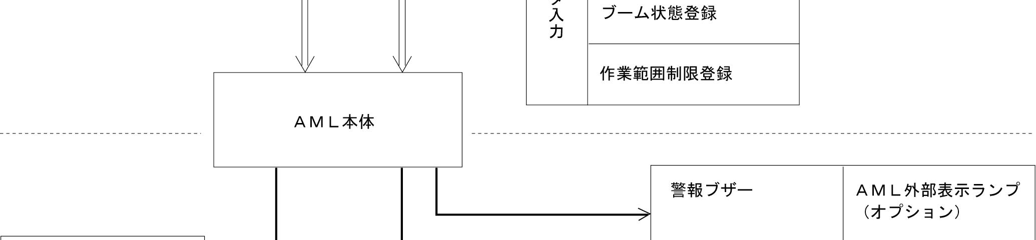
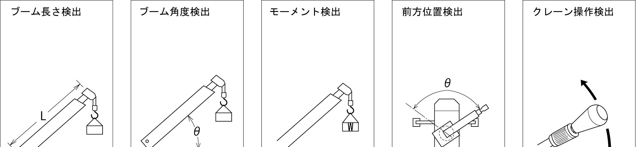
Configuration and Functions of the AML System
The AML system has various kinds of functions, including the following five typical functions. Based on the work conditions registered in the AML and the signals from various sensors, these functions control the crane operations.
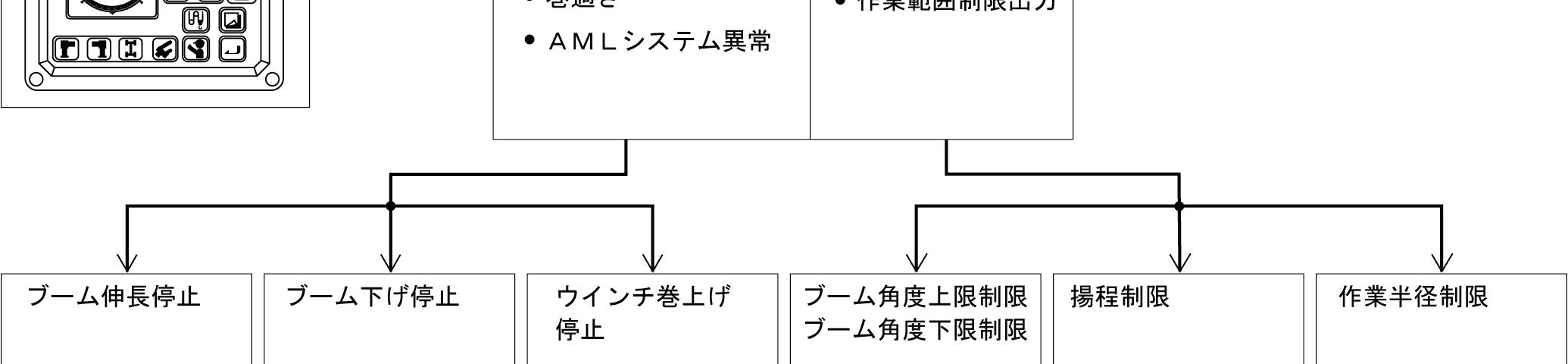
1. Automatic stop function to prevent overloading
The AML calculates and compares the working and rated moment values and displays their ratio. When the working moment exceeds the rated moment (100% or more), failure message is shown, alarm buzzer sounds, and the crane operation toward the critical side stops.
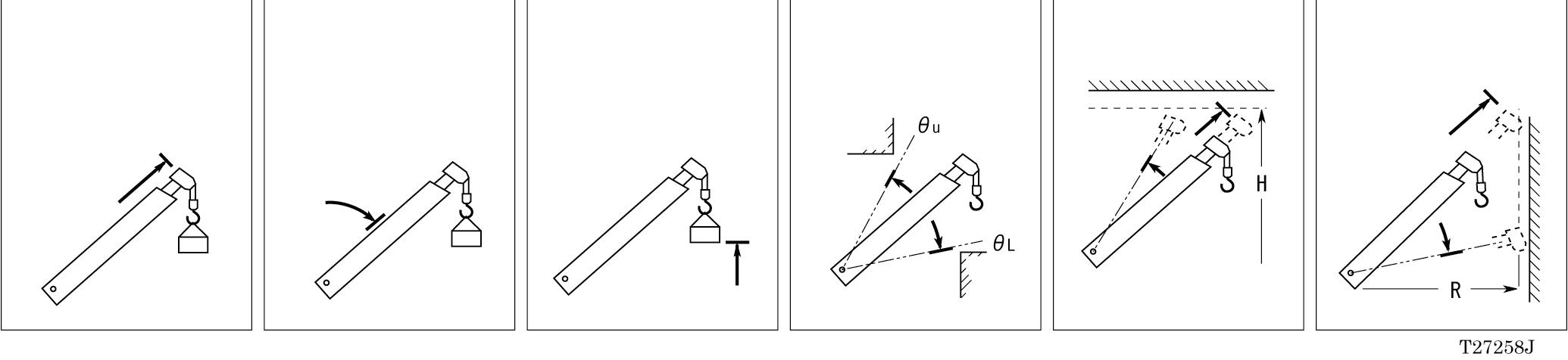
2. Working area limit functions
When any working area limit is registered to the AML, the crane is controlled so that the crane work posture does not exceed this registered working area limit. When the crane reaches the registered limit, failure message is shown, alarm buzzer sounds, and the crane operation stops.
3. Automatic stop function to prevent overwinding
When the hook block is overwound, the hoisting-up operation of the crane is stopped.
4. Automatic stop function for the backward stability
When the backward stability control is activated, the crane operation toward critical side is stopped. Not used in this machine.
The availability of the above described automatic stop function and working area limit functions is as shown in the table below depending on the individual operation. Be careful that turning the AML emergency switch to "非常用," and the crane starter switch to "ON" will change the center warning lamp to "AML warning" state and deactivate all the above AML stop functions (the troubleshooting function of the system).
On-outrigger operation
Stop at the stroke end Boom raising/lowering
Stop by working area limit
Boom raising/lowering
Boom extension
: Stop : No stop
5. Alarm Functions Condition Alarm
OverwindingBuzzer: Sounds continuously.
Crane is operated toward the critical side with the hook block overwound
Moment display: Displays an error message.
Moment load factor 100% or more
Crane is operated toward the critical side with moment load factor of 100% or more.
Crane operation control required
Working area limit function activated
AML system error
Moment display: Applicable bargraph is lit yellow (*1).
Buzzer: Sounds intermittently.
Buzzer: Continuous tremolo sound Moment load factor 90% or more and less than 100%
Moment display: Applicable bargraph is lit red until the moment load factor is up to 110% (*1). When 110% is exceeded, all the bargraphs are lit.
Buzzer: Sounds continuously.
Moment display: Displays an error message.
AML external indicator lamp: Lights red.
Buzzer: Sounds continuously.
Moment display: Displays the control message.
Buzzer: Beep (only for 3 seconds)
The corresponding limit indicator lamp flashes.
Buzzer: Beep (only for 3 seconds)
Moment display: Displays an error message.
Buzzer: Beep (only for 3 seconds)
*1: Refers to the seal area on the moment display.
Functions of and How to Use User Mode ( TS-75M-1 )
- Moment load factor is 100% or more.
- Overwinding occurs.
- AML system error
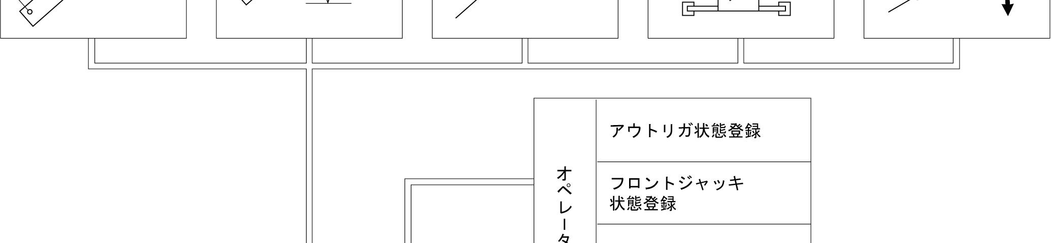
Operator input
Registration of the outrigger condition
Registration of the front jack condition
Registration of the lift status
Registration of the working area limits
Alarm buzzer AML external indicator lamps (option)
- The working area limit signal is output.
Functions of and How to Use User Mode ( TS-75M-1 )
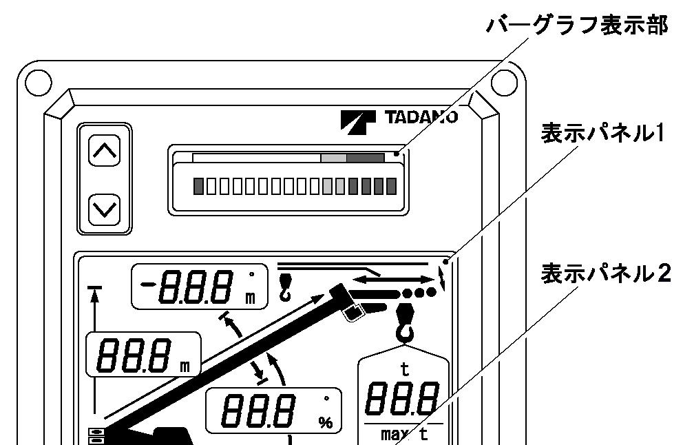
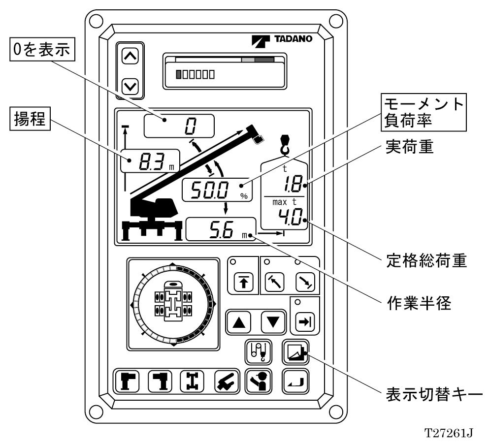
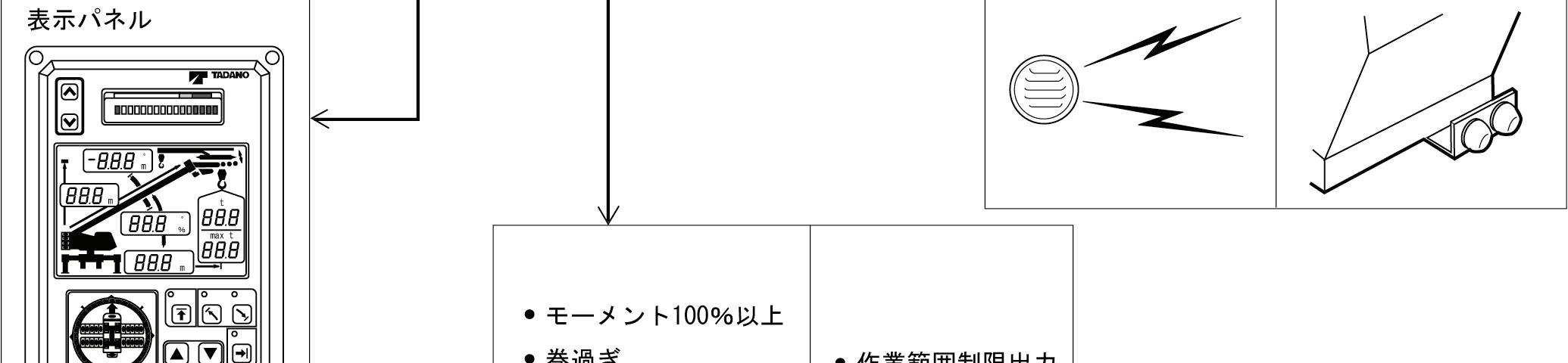
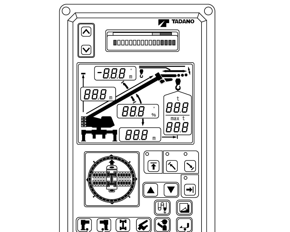
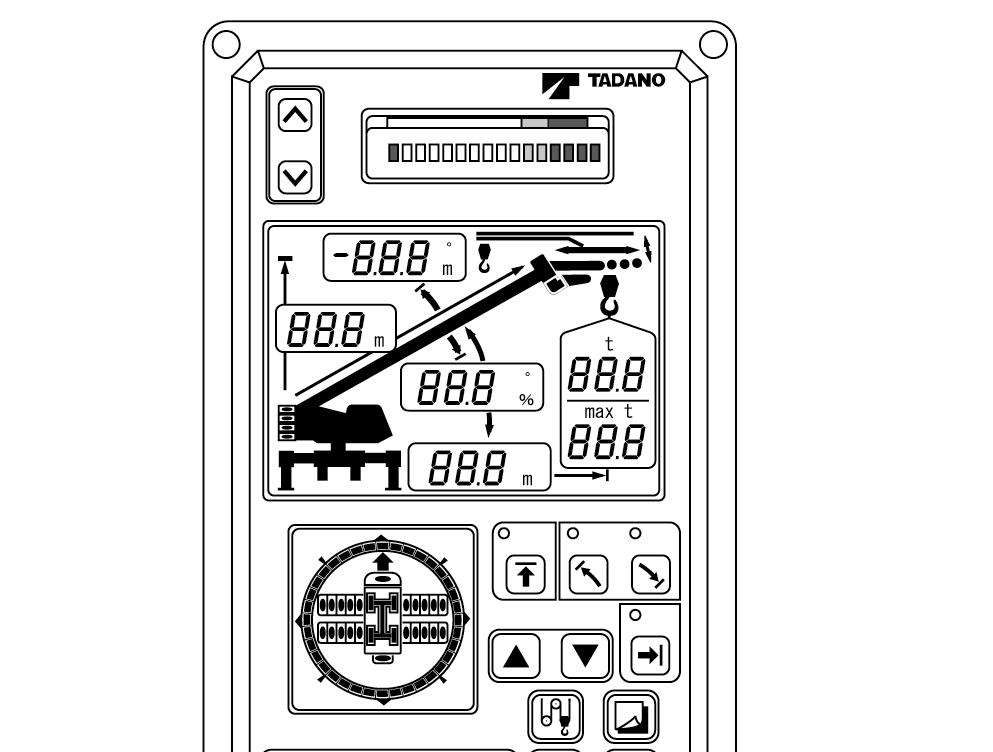
Names and Functions of the Parts
AML (Main Unit) A.
1. Load factor mark
The moment load factors on the bargraph are color coded as follows: safe (green), notice (yellow) and limit (red)
2. Moment display
Normally displays a moment load factor on a bargraph and in value. Also displays error messages when detects an error in a detector or others.
3. Scroll-up key (↑)
Used to see the previous lines of message displayed on the moment display.
4. Scroll-down key (↓)
Used to see the next lines of message displayed on the moment display.
B. Display panel 1
1. Boom length symbol
This symbol indicates that the boom length display 20 is showing the boom length.
2. Jib length symbol
Not used in this machine.
3. Jib angle symbol
Not used in this machine.
4. Jib lift symbol
Not used in this machine.
5. Actual load display
Displays the actual load.
6. Rated lifting capacity display
Displays the rated lifting capacity.
7. Load radius limit symbol
This symbol indicates that the load radius display 9 is showing the registered load radius limit value. The load radius symbol 8 is also lit at the same time when this symbol is lit.
8. Load radius symbol
This symbol indicates that the load radius display 9 is showing the load radius.
9. Load radius display
Normally displays the crane’s load radius. When the load radius limit function is activated, the registered load radius limit value is displayed while the set key is pressed.
10. Boom angle display
Normally displays the boom angle. When the lower limit function of boom angle is activated, the registered limit value is displayed while the set key is pressed.
11, 12. Boom angle symbols
This symbol indicates that the boom angle display 10 is showing the boom angle.
13. Single top lift symbol
This symbol indicates that the single top performance is selected.
14. Boom lift symbol
This symbol indicates that the boom lift is selected.
15, 16. Lower boom angle limit symbols
This symbol indicates that the boom angle display 10 is showing the registered lower boom angle limit value.
17, 18. Upper boom angle limit symbols
This symbol indicates that the boom angle display 23 is showing the registered upper boom angle limit value.
19. Counterweight condition symbol
Not used in this machine
20. Boom length display
Normally displays the boom length. Displays the lifting height while the display alteration key is pressed. When the lifting height limit function is activated, the registered limit value is displayed while the set key is pressed.
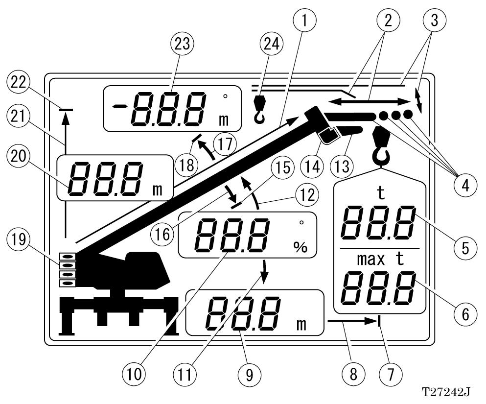
21. Lifting height symbol
This symbol indicates that the boom length display 20 is showing the lifting height.
22. Lifting height limit symbol
This symbol indicates that the boom length display 20 is showing the registered lifting height limit value. The lifting height symbol 21 is lit at the same time when this symbol is lit.
23. Jib angle display
When the upper boom angle limit function is activated, the upper boom angle limit value is displayed while the set key is pressed.
24. Number of part lines symbol
Not used in this machine.
C. Controls section
1. Left outrigger condition selector key
Used to select the left outrigger extension status.
2. Right outrigger condition selector key
Used to select the right outrigger extension status.
3. On-rubber condition selector key
Not used in this machine.
If the key is pressed unexpectedly, the machine moves to the on-rubber registration standby status. (The on-rubber condition symbol flashes.) Press the display alteration key 7 to return to the original state.
4. Lift status selector key
Used to select the lift status.
5. Inspection key
Used to perform the pre-operational inspection of the AML system.
6. Set key
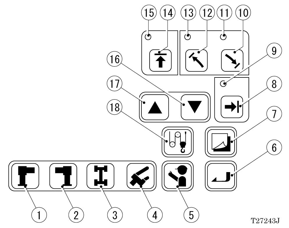
Used to register a selected status.
7. Display alteration key
Used to alter the displays on display panel 1.
8. Load radius limit key
Used to activate and release the load radius limiting function.
9. Load radius limit indicator lamp Lights when the load radius limiting function is activated.
10. Lower boom angle limit key
Used to activate and release the lowermost boom angle limiting function.
11. Lower boom angle limit indicator lamp Lights when the lower boom angle limiting function is registered.
12. Upper boom angle limit key
Used to activate and release the uppermost boom angle limiting function.
13. Upper boom angle limit indicator lamp Lights when the upper boom angle limiting function is registered.
14. Lifting height limit key
Used to activate and release the lifting height limiting function.
15. Lifting height limit indicator lamp Lights when lifting height limiting function is activated.
16. Increase key
Not used in this machine
17. Decrease key
Not used in this machine
18. Number of part-lines key
Not used in this machine.
If the key is pressed unexpectedly, the message [ロープデータガアリマセン] appears. Press the display alteration key 7 to return to the original state.
D. Display panel 2
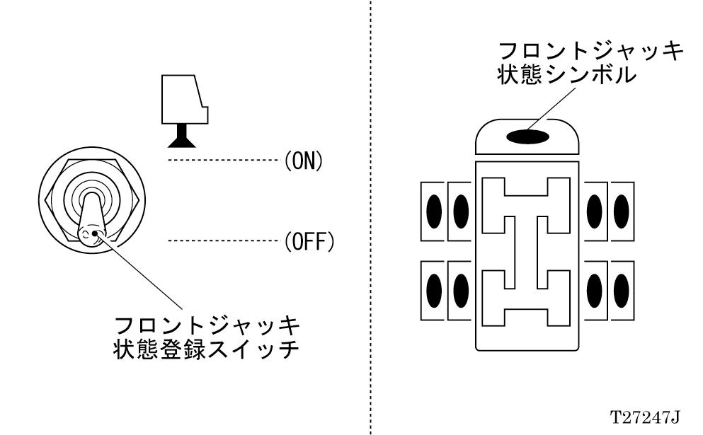
6. Front jack condition symbol
Lights when the front jack condition register switch is ON, indicating that the front jack using status has been registered.
7. Rear jack condition symbol
Not used in this machine.
1. Front position symbol
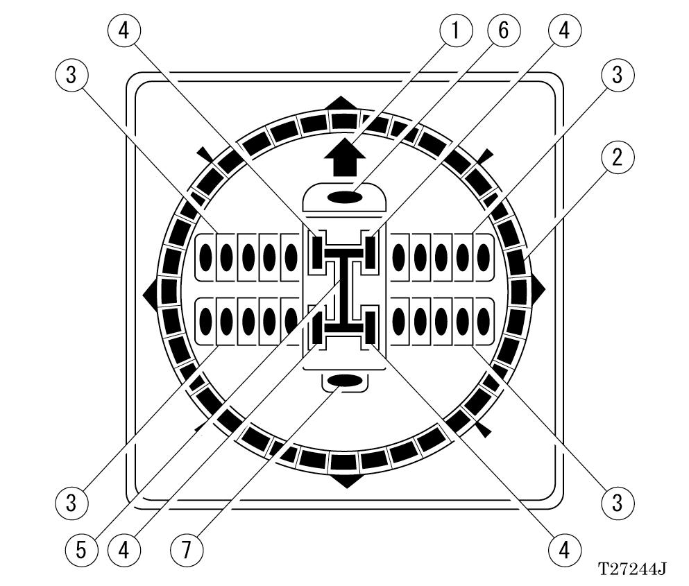
Lights when the swing position comes to the front position, indicating front area operation.
2. Swing position display
Displays the swing position of the boom for the right and left sides respectively.
Swing position: Right Swing position: Left
3. Outrigger condition symbol
Indicates the outrigger extension condition by symbol.
Flashes while the on-outrigger condition is being registered, and stays lit after the registration is completed.
4. On-rubber condition symbol
Lights when the power is ON.
5. Suspension lock condition symbol
Not used in this machine.
Registering Operating Conditions
Warning
Should the operational status be incorrectly registered, the crane may overturn or be damaged, leading to a serious accident. Prior to every operation, check that the registered status corresponds to the actual status of the crane.
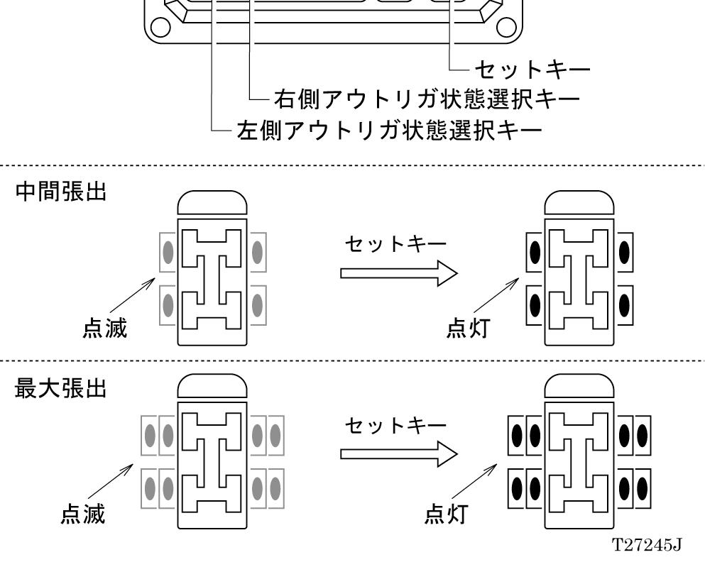
Registration of Outrigger Condition
[NOTICE]
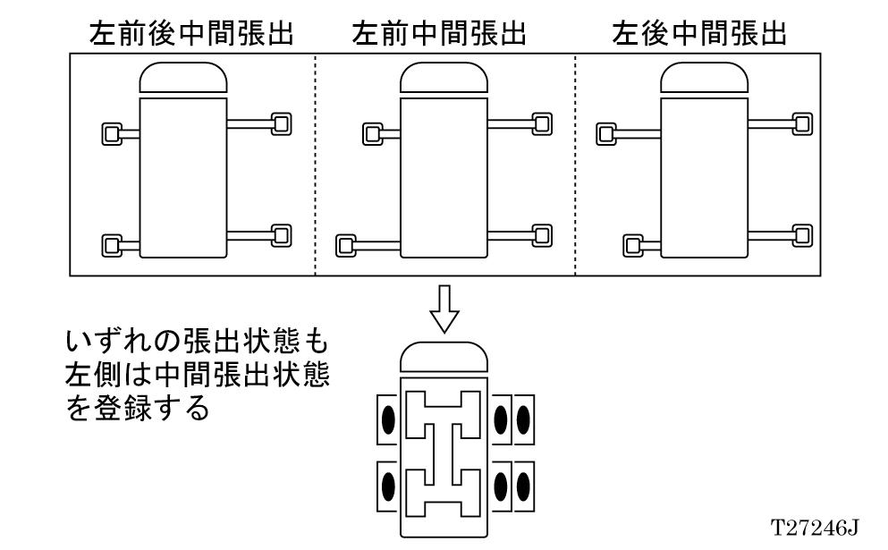
Register right and left outrigger condition separately on the AML. If the front and rear outrigger extension widths differ, register the smaller extension width as shown in the figure below.
The outrigger condition symbol changes from "flashing" to "being lit" to indicate that the condition has been successfully registered.
When the power supply is turned on, the on-rubber condition symbol is automatically lit.
Even after the power supply is turned off, the registered data is stored, and when the power supply is turned on again, the system is resumed with the registered operation status. However, the maximum storage period is 2 hours. If 2 hours or more have passed before the next power on, the registered data is erased. To resume the operation, register the settings all over again.
To register the outrigger condition, use the outrigger condition selector key and set key. Each time the outrigger condition selector key is pressed, the outrigger condition symbol flashes with alternate display of "Middle extension" → "Maximum extension" → "Middle extension" → "Maximum extension." After adjusting the right and left symbol display to the actual outrigger extension, press the set key.
Registration of Front Jack Condition
To register the front jack condition, use the front jack condition register switch.
1. When the front jack is used: Set the front jack condition register switch to (ON). The front jack condition symbol will light, indicating that the front jack condition has been registered.
2. When the front jack is not used: Turn the front jack condition register switch to (OFF).
Registration of Lift Status [NOTICE]
When the power supply is turned on, the boom lift is automatically selected. Even after the power supply is turned off, the registered data is stored, and when the power supply is turned on again, the system is resumed with the registered operation status. However, the maximum storage period is 2 hours. If 2 hours or more have passed before the next power on, the registered data is erased. To resume the operation, register the settings all over again.
To register the lift status, use the lift status selector key and set key.
Each time the lift status selector key is pressed, the display alternates in the sequence of "ブーム" → "シ
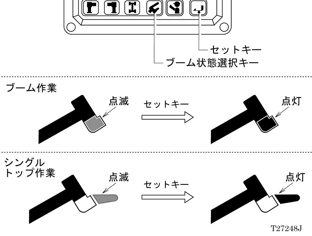
ングルトップ" → "ブーム" → "シングルトップ" …
After adjusting the working lift status, press the set key.
The symbol changes from "flashing" to "being lit," and the registration of the lift status is completed. The numerical value corresponding to the crane load radius display registered to the AML is displayed on the load display, rated load display, and load radius display.
Functions of and How to Use User Mode ( TS-75M-1 )
Display Alteration Operation
While the display alteration key is being pressed, the contents displayed on the display panel 1 can be altered. At the same time, the indicated symbol is displayed according to the displayed contents.
[NOTICE]
The displays enclosed by square as shown in the figure change. Even if the display alteration key is pressed, the contents displayed on the actual load display, rated lifting capacity display, and load radius display will not change.
Although "0" is displayed on the jib angle display, it has no particular meaning in case of this machine.