Control and operation
Operating manual
Installation and removal of the counterweight
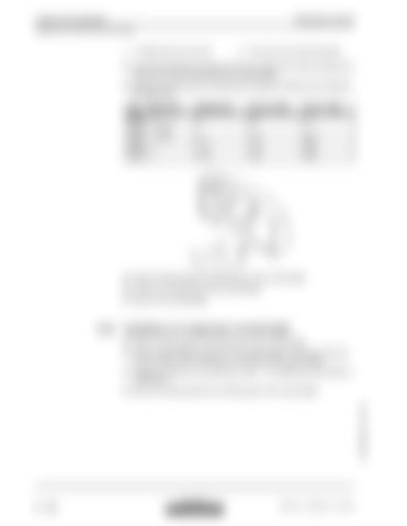
1
Threaded hole with eye bolt
2
Eye hook in the transverse girder
Choose the lifting gear and devices to have an angle of 60° minimum between the upper face of the counterweight and the lifting slings. Determine the lifting device considering the weights and lifting forces indicated in the table below. Type - lifting point
Weight [To]
Force F [kN]
Force T [kN]
R944C - 2 R954C - 1 and 2
9
90
52
R954C - 1 and 2
11
110
63,5
R954C - 1
11,5
115
66,4
R954C - 1
14,5
145
83,8
Attach the lifting slings to the lifting points of the counterweight. Loose the mounting bolts of the counterweight. Remove the counterweight.
3.9.2
Installation of a single-piece counterweight Attach the lifting slings to the lifting points of the counterweight. Lift the counterweight and place it on the uppercarriage. If mounted, check the correct insertion of the centring pins in the bores of the uppercarriage. Engage and tighten the mounting bolts. (M36 - 10.9; tightening torque 3300 N.m / 2430 ft.lbs). Remove the lifting slings from the lifting points of the counterweight.
copyright by
3 - 148
MJFCIFSS
ER 954 C - High-Rise / 11211691


