5 minute read
Control and operation
Note!
Increased wear.
Do not use the positioning swing brake purely as a service brake, but only as a stop and parking brake.
Using this brake to stop the uppercarriage running at the full swing RPM is not permissible since this would result in a quick abrasion of the brake discs.
In any case, first use the hydraulic braking to greatly reduce the speed of the uppercarriage
Depress the pedal 10 when the uppercarriage is near standstill
The uppercarriage can be stopped precisely and progressively in the desired position.
3.4.8 Working position
Work on a level, flat and firm ground. If necessary arrange the working place and free it of obstacles.
As a general rule, work with the attachment over the idler wheels.
Note!
Position the undercarriage so that it is situated lenghtwise to the working attachment and with the sprocket wheels at the rear, when the load is at its maximum reach during the working cycle.
3.4.9Working attachment control
Caution!
The joystick functions described below refer to the normal control, fitting out the machine at delivery.and according to ISO-standards, On machines equiped in addition with a special control system, and if this special control system is activated by the operator, the joystick functions correspond to the information on the label which is sticked on the side window of the cab and is specific to the installed special control system.
Control of the stick cylinder
Fig. 3-85 Stick cylinder control
The stick cylinder is operated using the left joystick 4 Pull the joystick 4 back (a) The stick is moved in. Push the joystick 4 forwards (b) The stick is moved out.
Control of the boom cylinders
The boom cylinders are operated using the right joystick 3
Pull the joystick 3 back (g) The working attachment is raised. Push the joystick 3 forwards (h). The working attachment is lowered.
Control of the grapple cylinders
The grapple cylinders are controlled by the right joystick 3.
Push the joystick 3 to the left e The the grapple closes. Push the joystick 3 to the right f The grapple opens.
Danger
Never allow anybody to guide the grapple by hand!
Combined movements
A diagonal movement of the joystick combines the corresponding movements of the working attachment. This makes it possible for all attachment movements to be actuated at the same time.
3.4.10Lowering the working attachment with the engine shut down
In an emergency, the attachment can be lowered also when the engine is not running.
Note
The attachment can be lowered thanks to a pressure accumulator mounted to the control oil unit. Due to the small volume of this accumulator only a limited number of movements can be actuated by the pilot control devices. Only operate the joysticks in the directions for lowering the attachment. Only the movements resulting from the own weight of the attachment parts are possible.
Turn the ignition key to contact position 1
Actuate the desired movement(s) while deflecting the joysticks (eventually also the foot pedals in case of special attachment) until the equipment has lowered to the required position.
3.4.11Rotating, tilting, locking and unlocking a working tool
An additional hydraulic circuit must be activated to operate some specific working tools such as:
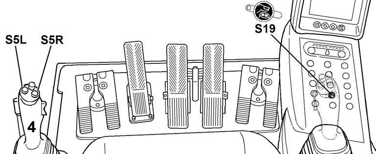
The medium pressure circuit is activated via the touch S19 on the main control unit.
The working tool is then actuated via the both push buttons S5L and S5R mounted at the top of the handle of the left joystick 4
Press the touch S19.
The medium pressure circuit is activated. The LED of the touch is lighting.
Press the left push button S5L and keep it pressed. The working tool is actuated to the left (the grapple is rotated to the left, or the bucket is swivelled to the left, or the locking pins of the hydraulic quick-change adapter are driving out, ...).
Fig. 3-89 Actuation of working tools
Press the right push button S5R and keep it pressed. The working tool is actuated to the right (the grapple is rotated to the right, or the bucket is swivelled to the right, or the locking pins of the hydraulic quickchange adapter are retracted, ...).
The movement of the working tool is stopped as soon as the push button S5L or S5R is released.
Press the touch S19 again. The medium pressure circuit is deactivated and the working tool can not be actuated any more. The LED of the touch goes out.
Note!
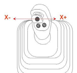
With the option "Left joystick with proportional control" installed, the working tool can be actuated in a proportional way, while deflecting the mini joystick A185 on the left joystick to the left X- or to the right X+
Caution!
On machines destined to the North American market, and which are fitted with a lifting magnet, the rotating device is controlled by the push buttons S6L and S6R in the handle of the right joystick 3. Also see the section "joysticks" in this chapter.
3.4.12Control of additional attachments via the additional pedals
If necessary, select the mounted additional attachment in the menu "Set Option". This selection determines pressure and oil flow adjustment in the hydraulic circuit, depending on the function and the size of the auxiliary user. A wrong selection could lead to damage or unsatisfactory operation of the additional attachment.
Note!
The selection of the attachment does neither have an influence upon the allocation of the pedals, nor lead to the switching-off of pedal function.
Danger!
Additional pedals may have many functions. They are describe on the operating sign in the cab, on the window on attachment side.
you start up a machine fitted with additional attachments.
Control of the other additional attachments
The additional pedal 9m/9k allows to control optionaly mounted additional attachments. These additional attachments are, for example:
When two of these additional attachments are mounted simultaneously on the machine, the first is controlled by the left double pedal 9m/9k, and the second is controlled by the right double pedal 9n/9p.
Push down the foot pedal 9m (or 9n). The cylinder of the additional user is retracted. Push down the foot pedal 9k (or 9p). The cylinder of the additional user is extended.
Control of a bottom dump shovel
For the excavators R934C - R944C - R954:
Push down the foot pedal 9p The shovel flap closes.
Push down the foot pedal 9n The shovel flap opens.
For the excavators R964C - R974C:
Push down the foot pedal 9n The shovel flap closes.

Push down the foot pedal 9p The shovel flap opens.
Control of the hydraulic hammer
Select the mounted hydraulic hammer in the menu "Set Option" The designation appears in the lower right corner of the screen (for example HM 2000).
In case of a doubt, contact your supervisor to obtain this information.
Push down the foot pedal 9m The hydraulic hammer is activated.
Note!
If the machine is used frequently or for long periods for hammer work, the hydraulic oil will be more contaminated than in usual conditions. Adapt the maintenance intervals for hydraulic oil and for return filter cartridges to the work in heavy dust conditions.
3.4.13AHS11 proportional control (option)
With the special equipment "AHS11 proportional control", installed on customer's request and according to customer's wishes, the AHS11 control on the left double pedal is permanently transfer on the axes X(-) and X(+) of the mini joystick on the right joystick.
Danger!
Risk of accident due to an unintentional movement by an uninformed machine operator!
With the AHS11 proportional control turned on, the correspondence between actuated controls and triggered working movements is changed. It is the responsibility of the owner of the machine to authorize an operator to operate the machine with the AHS11 proportional control.
Actuate the mini joystick to X(-) and keep it tilted: The cylinder of the additional equipment is extended and the additional equipment is moved correspondingly.
Actuate the mini joystick to X(+) and keep it tilted: The cylinder of the additional equipment is retracted and the additional equipment is moved correspondingly.


