D - HYDRAULIC ATTACHMENT AND MANUAL LOCKING DEVICE
- Stop the engine. - Relieve the pressure from the attachment hydraulic circuit by operating the hydraulic control lever (1)(fig. E) several times. - Connect the quick-connectors as needed for the attachment’s hydraulic movements. IMPORTANT: Make sure that the quick-connectors are clean, and protect the connections that are not used with the caps provided.
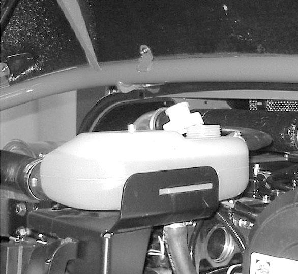
CT6-18 INSTALLING AN ATTACHMENT - Ensure that the attachment is in a position for locking it to the carriage. If it is not correctly oriented, take the necessary precautions to safely position it. - Check that the locking pin and the clip are in position in the bracket (fig. A).
MANUAL RELEASING AND DISCONNECTING THE ATTACHMENT - Proceed in the reverse order of paragraph MANUAL LOCKING AND CONNECTING THE ATTACHMENT. Be sure to reinstall the locking pin and the clip in the bracket (fig. A). REMOVING AN ATTACHMENT - Proceed in the reverse order of paragraph INSTALLING AN ATTACHMENT. Be sure to place the attachment flat on the ground and in a closed position.
A
- Park the telescopic handler with the boom lowered in front of and in line with the attachment. Tilt the carriage forwards (fig. B). - Bring the carriage under the mounting tube of the attachment, slightly lift the boom, and tilt the carriage rearward to position the attachment (fig. C). B
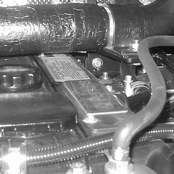
E - HYDRAULIC ATTACHMENT AND HYDRAULIC LOCKING DEVICE CT6-18 Turbo INSTALLING AN ATTACHMENT - Ensure that the attachment is in a position for locking it to the carriage. If it is not correctly oriented, take the necessary precautions to safely position it. - Check that the pins (1) on the locking cylinder are retracted (fig. A). - Park the telescopic handler with the boom lowered in front of and in line with the attachment. Tilt the carriage forward (fig. B).
C
A
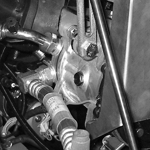
- Lift the attachment off the ground to ease locking. MANUAL LOCKING AND CONNECTING THE ATTACHMENT - Remove the locking pin and the clip from the bracket (fig. A) and lock on the attachment (fig. D). Do not forget to replace the clip. D
1
1
E
- Bring the carriage under the locking tube of the attachment, slightly lift the boom, and tilt the carriage rearward to position the attachment (fig. C).
1
PRINTED IN U.S.A.
B
83
913223/BP0206