6 minute read
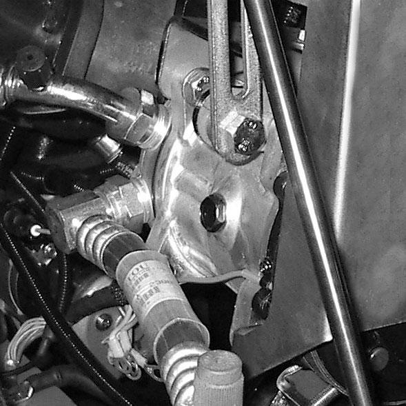
C -SWITCH FOR ALIGNMENT OF THE WHEELS

from Gehl CT6-18 Low Profile CT6-18 Turbo Telescopic Handler Operator's Manual 913223 - PDF DOWNLOAD

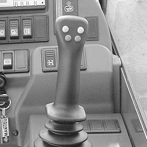
CT6-18 with Loader-Type Controls
LIFTING ALOAD
-Pull lever Arearward to raise the boom.
-Push lever Aforward to lower the boom.
TILTING THE CARRIAGE
-Move lever Ato the left for rearward tilt.
-Move lever Ato the right for forward tilt.
TELESCOPING THE BOOM
-Push lever B forward to extend the boom.
-Pull lever B rearward to retract the boom.
ATTACHMENTOPERATION
This switch enables alignment of the wheels. The indicator lamp indicates if it is ON.
WHEELALIGNMENTPROCEDURE
-Press the switch (signal lamp ON).
-Shift the hydraulic valve control lever for steering selection Ato position A2 (4-wheel steering).
-Turn the steering wheel and bring the rear wheels into alignment until the lamp B2 is ON.
-Shift the hydraulic valve control lever for steering selection Ato position A1 (highway use).
-Turn the steering wheel and bring the front wheels into alignment until the lamp B1 is ON.

Warning
Before driving on roads, it is necessary to check the alignment of the rear wheels and to select front-wheel steering mode. The alignment of the rear wheels must be done regularly while driving the telescopic handler, with the help of the green lamps. In case of problems, consult your dealer.
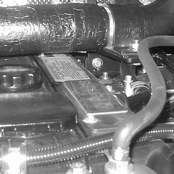
20 -HYDRAULIC CONTROLS AND TRANSMISSION CUT-OFF
IMPORTANT : Do not attempt to alter the hydraulic system pressure by adjusting the pressure regulating valve. In the event of suspected malfunction, contact your dealer. ANYALTERATION MAYVOID THE WARRANTY.
Warning
Use the hydraulic controls carefully without jerking, to avoid accidents caused by sudden movement of the telescopic handler.
-Move lever C forward or rearward to actuate a hydraulic attachment.
TRANSMISSION CUT-OFF
-Press button D (see: chapter 5 - INSTRUMENTS AND CONTROLS: 5 - SWITCH PANEL).
CT6-18 with “Pick-N-Place” Controls
LIFTING ALOAD
-Pull lever Arearward to raise the boom.
-Push lever Aforward to lower the boom.
TELESCOPING THE BOOM
-Move lever Ato the left to retract the boom.
-Move lever Ato the right to extend the boom.
TILTING THE CARRIAGE
-Push lever B forward to tilt the carriage forward.
-Pull lever B backward to tilt the carriage rearward.
ATTACHMENTOPERATION
-Move lever C forward or rearward to actuate a hydraulic attachment.
TRANSMISSION CUT-OFF
-Press button D (see: chapter 5 - INSTRUMENTS AND CONTROLS: 5 - SWITCH PANEL).
CT6-18 Turbo LIFTING ALOAD
-Pull lever Arearward to raise the boom.
-Push lever Aforward to lower the boom.
TILTING THE CARRIAGE
-Move lever Ato the left for rearward tilt.

-Move lever Ato the right for forward tilt.
TELESCOPING THE BOOM
-Press button B to extend the boom.
-Press button C to retract the boom.
ATTACHMENTOPERATION
-Press buttons D or E to actuate a hydraulic attachment..
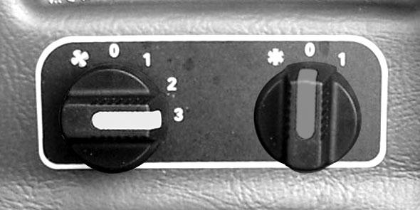
22 -HEATER CONTROLS

A- FAN CONTROL
This 3-speed control regulates the airflow through the vents.
B - TEMPERATURE CONTROL
This control is used to adjust the temperature in the cab.
B1 -With the valve closed, the fan delivers unheated air.
B2 -With the valve opened completely, the fan delivers fully heated air.
TRANSMISSION CUT-OFF
-Press button G (see: chapter 5 - INSTRUMENTS AND CONTROLS: 5 - SWITCH PANEL).
NOTE: If the hydraulic functions do not operate on CT6-18 Turbo machines, turn the steering wheel to recharge the hydraulic control accumulator and hydraulic functions should be restored.
21 -LOAD CHARTS
This flip chart includes the description of the hydraulic controls and the load charts for the attachments used on the telescopic handler.

The intermediate positions allow the temperature to be adjusted.
22 -HEATER / AIR CONDITIONER CONTROLS
IMPORTANT: The air conditioner only comes on when the telescopic handler has been started. When using the air conditioning, the doors and windows should be kept closed.
In cold weather: Warm the engine before switching on the compressor, to allow any refrigerant that has collected in the liquid state at the lowest point of the compressor circuit to turn into gas under the effect of the heat given off by the engine, because the compressor is likely to be damaged by liquid refrigerant.
In winter: To ensure proper operation and complete efficiency of the air conditioning unit, switch on the compressor once a week, if only briefly, to lubricate the internal seals.
IMPORTANT: If the air conditioner does not seem to be working properly, have it examined by your dealer (see chapter: 6 - MAINTENANCE: HEVERYTWO YEARS). Never try to repair any problems yourself.
Description Of The Air Conditioner Controls
A- Control with signal light indicating start-up and cut-out of the air conditioning system, if control "C" is in position 1, 2 or 3


B - Heating air temperature control
C - Air flow setting and fan speed control. In position "0" the air conditioning system no longer functions.

Defrosting Mode
The controls must be adjusted in the following way:
A- Control, with signal light on
B - At the selected temperature
C - At the selected fan speed 1, 2 or 3
NOTE: Possible losses of water under the telescopic handler are due to condensate discharges caused by the drying effect of the air conditioning, especially with high outside temperatures and high relative humidity.
For the air conditioner to perform properly, the air intakes must not be blocked by frost, snow or leaves.
When the air conditioner is running, at least one of the cab air vents must be open to avoid the risk of freezing the evaporator.
Heating Mode
The controls must be adjusted in the following way:
A- Control, with signal light off
B - At the selected temperature
C - At the selected fan speed 1, 2 or 3
See chapter: 6 - MAINTENANCE: D - EVERY500 HOURS SERVICE.
24 -WINDSHIELD DEFROSTER
Air Conditioning Mode
The controls must be adjusted in the following way:
A-Control, with signal light on
B - At the selected temperature
C - At the selected fan speed 1, 2 or 3
For optimum effectiveness, close the heater vents.
25 -HEATER VENTS
These heater vents enable the air to be directed to the interior of the cab and onto the side windows.

26
Two keys are provided with the telescopic handler to enable the cabin to be locked.


A- Left front indicator


B - Left front dipped headlight
C - Left front main beam
D - Left front sidelight
E - Right front indicator

F - Right front dipped headlight
G - Right front main beam
H - Right front sidelight

27
28
29
EMERGENCYEXIT
Use the rear window as an emergency exit, if it is not possible to leave the cab by the door.
A- Left rear indicator
B - Left rear stoplight
C - Left tail light
D - Left rear reverse light
E - Left rear fog light
F - Right rear fog light
G - Right rear reverse light
H - Right tail light
I - Right rear stoplight
J - Right rear indicator
30 -MANUALHOLDER
Ensure that the operator's manual is in its place in the document holder.
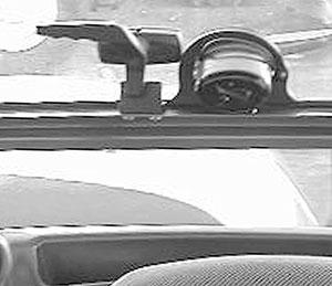
34 -INCLINOMETER
Enables the operator to check that the telescopic handler is in the horizontal position.
37 -RADIO
To prevent discharging the telescopic handler’s battery, the radio must be turned off when leaving the machine for extended periods of time. The radio remains on when the ignition key is turned to the “off” position. Press button (1) on the radio until the display on the radio turns off. Review the radio manual provided with the machine for further radio operation controls.

35 -STEERING WHEELPOSITIONING HANDLE - CT6-18 Turbo
This handle enables the angle and height of the steering wheel to be adjusted.
-Turn handle (1) toward Ato loosen and adjust steering wheel.
-Turn handle (1) toward B to lock steering wheel in the position required.

Tow Pin
36 -ARM REST - CT6-18 Turbo
The arm rest can be adjusted in height.
-Untighten screws (1) and adjust arm-rest to the height desired.
-Retighten screws (1).
Located at the rear of the telescopic handler, this device is used to attach a trailer. Its capacity is limited for each telescopic handler by the authorized gross vehicle weight, tractive effort and maximum vertical force on the coupling point. This information is given on the manufacturer's plate fixed to each telescopic handler (see chapter: 1 - SPECIFICATIONS AND CONTROLS: IDENTIFICATION OF THE TELESCOPIC HANDLER).


-To use a trailer, see current regulations in your state/province (maximum running speed, braking, maximum weight of trailer, etc.).
-Verify the trailer's condition before using it (tire condition and pressures, electrical connection, hydraulic hose, braking system).
Warning
Do not tow a trailer that is not in good working condition. Using a trailer in poor condition may affect the telescopic handler's steering and braking, and cause an accident.
Warning
If an assistant helps in connecting or disconnecting the trailer, this person must always be visible to the operator and wait until the telescopic handler has stopped, the parking brake is applied and the engine is stopped before performing the operation.
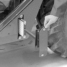
A-TOW PIN

CONNECTING AND DISCONNECTING ATRAILER
-To connect a trailer, position the telescopic handler as close as possible to the trailer hitch ring.
-Apply the parking brake and turn off the engine.
-Remove the clip (1,) lift the tow pin (2) and insert (or remove) the trailer hitch ring.
B -TRAILER ELECTRIC CONNECTOR
This 7-pin connector enables electrical power supply connection for a trailer or signal bar.
Warning
Be careful not to get your fingers caught or crushed during this operation.
Do not forget to put clip (1) back in place.
When uncoupling, make sure that the trailer is independently supported.
A- Left turn indicator
C - Ground
D - Right turn indicator
E - Right tail light
F - Rear stoplight
G - Left tail light