36 minute read
Chapter 3 SAFETY

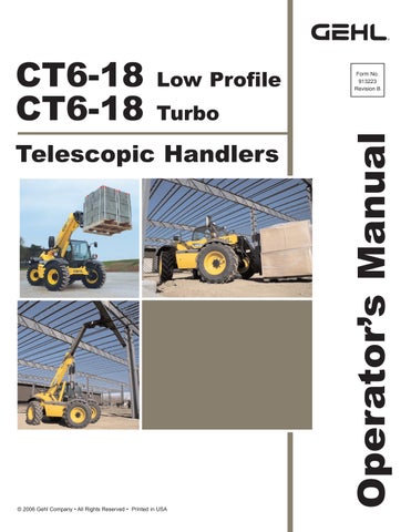
from Gehl CT6-18 Low Profile CT6-18 Turbo Telescopic Handler Operator's Manual 913223 - PDF DOWNLOAD

Generalinstructions
Before operating this equipment, read and study the following safety information. In addition, be sure that everyone who operates or works with this equipment, is familiar with these safety precautions.
WHENEVER YOU SEE THIS SYMBOL: IT MEANS: WARNING! BE CAREFUL! YOUR SAFETYOR THE SAFETYOF THE TELESCOPIC HANDLER IS AT RISK.
Warning
The risk of accident while using, servicing and repairing the telescopic handler can be minimized by following the safety warnings and instructions detailed in this manual.
Gehl Company has ensured that this telescopic handler is suitable for use under normal operating conditions defined in this Operator's Manual and in accordance with safety standard ANSI/ASME B56.6. Before using the telescopic handler, the owner must make sure that the telescopic handler is appropriate for the work to be done.
In addition to standard equipment mounted on the telescopic handler, many options are available, such as: flashing lights, front light, rear light, light at the boom head, etc.
The operator must take into account the operating conditions to determine the necessary signalling and lighting equipment. Contact your dealer for information.
GEHLCompany always takes the operator’s safety into consideration when designing its machinery, and guards exposed moving parts for his/her protection. However, some areas cannot be guarded in order to assure proper operation. Further, this Operator’s Manual and decals on the machine warn of additional hazards and should be read and observed closely. It is the owner’s responsibility for communicating information on the safe use and proper maintenance of this machine! This includes providing understandable interpretations of these instructions to operators who are not fluent in reading English.
Danger
“DANGER” indicates an imminently hazardous situation which, if not avoided, will result in death or serious injury.
Warning
“WARNING” indicates a potentially hazardous situation which, if not avoided, could result in death or serious injury.
Caution
“CAUTION” indicates a potentially hazardous situation which, if not avoided, may result in minor or moderate injury. It may also alert users to unsafe practices.
It is the responsibility of the operator to read and understand the Operator’s Manual and other information provided, and to use correct operating procedures. Machines should be operated only by qualified operators.
Mandatory Safety Shutdown Procedure
BEFORE cleaning, adjusting, lubricating or servicing the unit:
1.Stop machine on a level surface. (Avoid parking on a slope, but if necessary, park across the slope and block the tires.)
2.Fully retract the boom and lower the attachment tool to the ground. Idle engine for gradual cooling.
3.Place controls in neutral and apply parking brake.
4.Shut off the engine and remove the key.
ONLYwhen you have taken these precautions can you be sure it is safe to proceed. Failure to follow the above procedure could lead to death or serious bodily injury.
Warning
U.S. OSHAregulations require employers in general industry and the construction, shipyard and cargo-handling industries (excepting agricultural operations) to ensure that forklift operators are competent, as demonstrated by successful completion of a training course.
The training course must consist of a combination of formal instruction and practical training, including both forklift-related and workplace-related topics, and evaluation of the operator’s performance in the workplace.
All operator training and evaluation is to be conducted by persons who have the knowledge, training and experience to train and evaluate operators.
Warning
ALWAYS maintain a safe distance from electric power lines and avoid contact with any electrically charged conductor or gas line. It is not necessary to make direct contact with a power line for power to ground through the structure of the machine. Keep the boom at least 10 ft. (3 m) from all power lines. Accidental contact or rupture can result in electrocution or an explosion. Contact the North American One-Call Referral System at (888) 258-0808 for the local “Digger’s Hotline” number or proper local authorities for utility line locations BEFORE starting to dig!
Warning
The telescopic handler is designed for outdoor use under normal atmospheric conditions, and indoor use in suitably ventilated premises.
It is prohibited to use the telescopic handler in areas where there is a risk of fire or potentially explosive materials (e.g., refineries, fuel or gas depots, stores of flammable products) For use in these areas, specificly approved equipment is available. (Ask your dealer for information.)
Safetyreminders
User/operator safety practices,as established by industry standards, are included in this Operator’s Manual and intended to promote safe operation of the machine. These guidelines do not, of course, preclude the use of good judgment, care and common sense, as may be indicated by the particular jobsite work conditions.
It is essential that operators be physically and mentally free of mind-altering drugs and chemicals, and thoroughly trained in the safe operation of the machine. Such training should be presented completely to all new operators and not condensed for those claiming previous experience. Information on operator training is available from several sources, including the manufacturer.
Some illustrations used in this manual may show doors, guards and shields open or removed for illustration purposes ONLY. BE SURE that all doors, guards and shields are in their proper operating positions before starting the engine.
Only the operations and actions described in this operator's manual may be performed. The manufacturer cannot predict all possible risky situations. Consequently, the safety instructions in this operator's manual and on the telescopic handler itself are not 100% exhaustive, and operators must always consider the possible risks to themselves, to others and to the telescopic handler itself.
Atelescopic handler operating in an area without fire extinguishing equipment must be equipped with an individual extinguisher.
Warning
Failure to follow the safety and operating instructions, and the instructions for repairing and servicing the telescopic handler may lead to serious, or even fatal accidents.
Operator Instructions
A-OPERATOR'S MANUAL
Read the operator's manual carefully.
The operator's manual must always be in good condition and in the place provided for it on the telescopic handler.
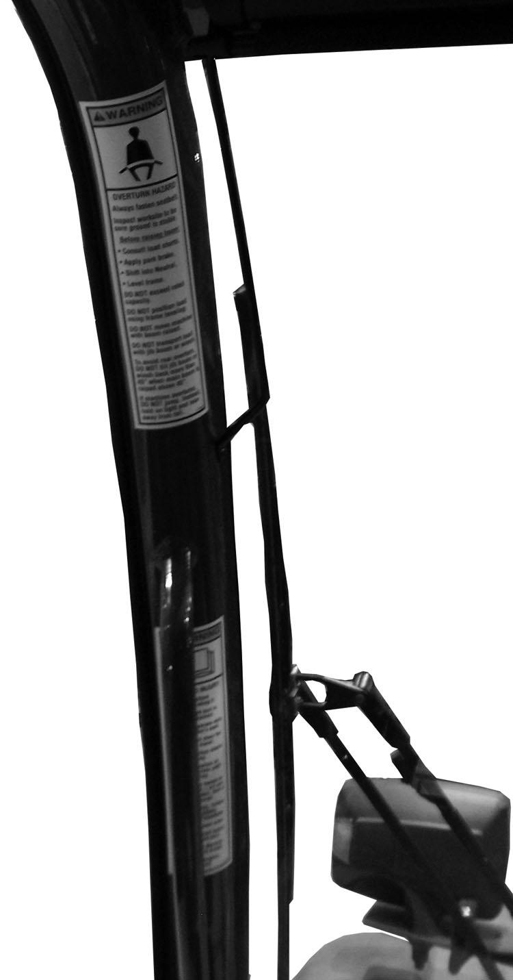
Report any warning decals that are no longer legible.
B -AUTHORIZATION FOR USE
Only qualified, trained and authorized personnel may use the telescopic handler. This authorization is given by the appropriate person in the company in charge of using the telescopic handler.
The operator is not allowed to authorize the use of the telescopic handler by another person.
Warning
There are a number of possible situations in which operating the telescopic handler is not allowed. Such abnormal uses are strictly forbidden. For example:
- Abnormal behavior resulting from carelessness.
- Behavior resulting from “doing it the easy way” when performing a task.
- Operation by such persons as: teenagers, handicapped persons, trainees tempted to drive a telescopic handler, and operators tempted to operate in a manner to win a bet, in competition or for their own personal experience.
The person in charge of the equipment must take these possibilities into account when assessing whether or not a person will make a suitable operator.
C -MAINTENANCE
Warning
The telescopic handler must be inspected periodically to ensure that it remains in good operating condition. The frequency of inspections is determined by usage and regulations of the country and state/province in which the telescopic handler is used.
The operator must immediately advise his supervisor if the telescopic handler is not in good working condition.
NEVER use your hands to search for hydraulic fluid leaks. Instead use a piece of paper or cardboard. Escaping fluid under pressure can be invisible and can penetrate the skin, causing serious injury. If any fluid is injected into your skin, see a doctor at once. Injected fluid MUSTbe surgically removed by a doctor familiar with this type of injury or gangrene may result.
ALWAYS wear safety glasses with side shields when striking metal against metal. In addition, it is recommended that a softer (chip-resistant) material be used to cushion the blow. Failure to heed could lead to serious injury to the eyes or other parts of the body.
Avoid lubrication or mechanical adjustments with the machine in motion or the engine running. If the engine must be running to make certain adjustments, position the equipment in a safe position, place the transmission in neutral, apply the parking brake, securely block the tires and use extreme caution.
The operator is prohibited from performing any repairs or adjustments unless he/she has been trained for this purpose.
The operator must keep the telescopic handler properly cleaned.
The operator must carry out daily maintenance (see: chapter: 6 - MAINTENANCE: A- DAILY OR EVERY10 HOURS SERVICE) if this is among his/her responsibilities.
The operator must ensure the tires are suitable for the nature of the ground (see contact surface area of the tires in chapter: 1 - SPECIFICATIONS: CHARACTERISTICS). Consult your dealer regarding: flotation tires, traction tires, snow chains.
Warning
Do not use the telescopic handler if the tires are incorrectly inflated, damaged or excessively worn, because this could put the operator’s safety or that of others at risk, or cause damage to the telescopic handler. The fitting of foam-filled tires is prohibited and is not warranted by the manufacturer without prior authorization.
To ensure continued safe operation, replace damaged or worn-out parts with genuine GEHLservice parts before using this equipment.
D -MODIFICATION OF THE TELESCOPIC HANDLER
Modifications and additions that affect capacity or safe operation must never be performed without the manufacturer’s prior written approval. Where such authorization is granted, any applicable markings are to be changed accordingly.
All attachment tools MUSTbe marked to identify the attachment tool and the total capacity with the attachment tool at maximum elevation with the load laterally centered.
Be sure all nameplates, warnings and instruction markings are in place and legible. Local government regulations may require specific equipment, which is the responsibility of the owner to provide. For the safety of the operator and others, do not change the structure or settings of the various components used in the telescopic handler (hydraulic pressure, calibrating limits, engine speed, addition of extra equipment, addition of counterweight, unapproved attachments, alarm systems, etc.). In this event, the manufacturer cannot be held responsible.
E -SAFETYGUARDS AND WARNING DEVICES
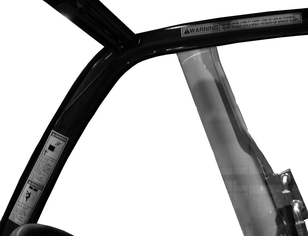
This machine is fitted with a Roll-Over Protective Structure (ROPS) and Falling Object Protective Structure (FOPS) in accordance with industry standards. It is intended to offer protection to the operator from falling objects and in case of an overturn, but it cannot protect against every possible hazard. Therefore, it should not be considered a substitute for good judgment and safe practices in operating the machine. If the ROPS / FOPS structure is damaged, it must be replaced to restore the protection it provides.
Chapter 4
Operating And Safetyinstructions
A-BEFORE STARTING THE TELESCOPIC HANDLER
Perform daily maintenance (see chapter: 6MAINTENANCE: A- DAILYOR EVERY10 HOURS SERVICE).
Make sure the lights, indicators and windshield wipers are working properly.
Make sure the rearview mirrors are in good condition, clean and properly adjusted.
Make sure the horn works.
Check brakes, steering, and hydraulic system prior to starting operation. Operate all controls to ensure proper operation. Observe all gauges and indicators for proper operation. If any malfunctions are found, correct the cause prior to using the machine.
ALWAYS wear appropriate personal protective equipment for the job and working conditions. Hard hats, goggles, protective shoes, gloves, reflector-type vests, respirators and ear protection are exampes of types of equipment that may be required. DO NOTwear loose-fitting clothing, long hair, jewelry or loose personal items while operating or servicing the machine.
ALWAYS check the job site for terrain hazards, obstructions and people. Remove all objects that do not belong in or on the machine and its equipment.
Walk around the machine and warn all personnel who may be servicing the machine or who are in the machine’s path prior to starting. DO NOTstart until all personnel are clearly away from the machine.
B -OPERATOR INSTRUCTIONS
Whatever his/her experience, the operator is advised to familiarize himself/herself with the location and operation of all the controls and instruments before operating the telescopic handler.
Wear clothes suited for operating the telescopic handler. Avoid loose clothing.
Make sure you have the appropriate personal protective equipment for the job.
Prolonged exposure to high noise levels may cause hearing problems. It is recommended to wear ear muffs to protect against excessive noise.
Always keep alert when using the telescopic handler. Do not listen to the radio or music using headphones or earphones.
Never operate the telescopic handler when hands or feet are wet or soiled with greasy substances. For increased comfort, ensure that the seat is adjusted to your requirements and in the correct position.
Warning
DO NOT adjust the seat while the telescopic handler is moving.
The operator must always be in the normal position in the cab. It is prohibited to have arms, legs or any part of the body protruding from the cab of the telescopic handler.
The seat belt must be worn and adjusted to the operator's size.
The controls must never be used for anything except their intended purposes (e.g., climbing onto or down from the telescopic handler).
If a control is equipped with a locking device, it is forbidden to leave the cab without first locking the control in neutral.
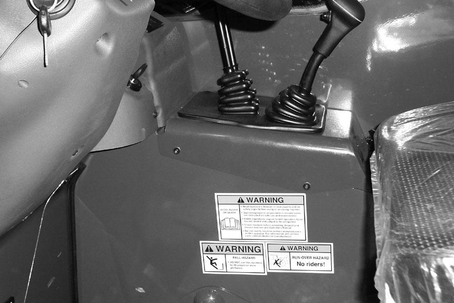
It is prohibited to carry passengers either on the telescopic handler or in the cab.
C -ENVIRONMENT
Comply with all work site safety rules.
If the telescopic handler must be used in a dark area or at night, make sure it is equipped with working lights.
During operation, make sure that no one is in the way of the telescopic handler and its load.
Do not allow anybody to come near the work area of the telescopic handler or pass under an elevated load.
When using the telescopic handler on a side slope, before lifting the boom, follow the instructions given in the paragraph: INSTRUCTIONS FOR HANDLING ALOAD: M - TRANSVERSE ATTITUDE OF THE TELESCOPIC HANDLER.
Travelling on a longitudinal slope :
•Drive and brake gently.
•Moving without a load: Forks or attachment facing downhill.
•Moving with a load: Forks or attachment facing uphill.
Never move onto a trailer without having first checked:
•That it is suitably positioned and made fast.
•That the unit to which it is connected (wagon, truck, etc.) will not shift.
•That the trailer is suitable for the total weight of the telescopic handler.
•That the trailer is suitable for the size of the telescopic handler.
Never move onto a bridge, floor or elevator, without being certain that it is suitable for the weight and size of the telescopic handler and without having checked that it is in good condition.
Be careful in the area of loading bays, trenches, scaffolding, soft ground and manholes.
Make sure the ground is stable and firm under the wheels and/or stabilizers before lifting or removing the load. If necessary, add sufficient wedging under the stabilizers, if equipped.
Make sure that the scaffolding, loading platform, pilings or ground is capable of bearing the load. Never stack loads on uneven ground, because they may tip over.
In the case of work near power lines, ensure that the safety distance is sufficient between the work area of the telescopic handler and the power lines.
Warning
You could be electrocuted or seriously injured if you operate or park the telescopic handler too close to power lines. Consult your local utilities.
Warning
In the event of high winds, do not perform work that jeopardizes the stability of the telescopic handler and its load, particularly if the load can be affected by the wind.
D -VISIBILITY
Maintain good visibility throughout the route. In reverse, either look directly behind or use the rearview mirrors. In any case, avoid driving in reverse over long distances.
Visibility may be reduced on the right side when the boom is raised, so before lifting the boom make sure that the movement can be made in complete safety.
If the forward visibility is not sufficient because of the bulkiness of the load, drive in reverse. This movement must be an exception and only done for short distances.
Ensure good visibility (clean windows, adequate lighting, correctly adjusted rearview mirrors, etc.).
If visibility of the road is inadequate, ask someone to help, standing outside the area in which the machine will be moving, and making sure you always have a good view of this person.
E -STARTING THE TELESCOPIC HANDLER
Warning
The telescopic handler must only be started or moved when the operator is sitting in the cab with the seat belt fastened and adjusted.
Never try to start the telescopic handler by pushing or towing it. Such operation may cause severe damage to the transmission. If it’s necessary to tow the telescopic handler in an emergency, the transmission must be placed in neutral (see chapter: 6MAINTENANCE: G - PERIODIC MAINTENANCE).
Check for closing and locking of covers.
Make sure that the forward/reverse lever is in neutral.
Turn the ignition key to position “I” to activate the electrical system.
Make sure the signal lights on the instrument panel and fuel level indicators are working properly (see chapter: 5 - INSTRUMENTS AND CONTROLS: 3 - CONTROLAND SIGNALLAMPPANEL).
Turn the ignition key to position “II” to preheat for 15 seconds and then turn the ignition key fully; the engine should then start. Release the ignition key and let the engine run at idle.
Do not engage the starter motor for more than 15 seconds. Carry out the preheating for 10 seconds between unsuccessful attempts.
Make sure all the signal lamps on the instrument panel are off.
Check all instruments when the engine is warm and at regular intervals during use, to detect any faults and be able to correct them without delay.
If an instrument does not show the correct display, stop the engine and immediately carry out the necessary corrections.
Warning
The electrolyte in the battery may produce an explosive gas. Avoid open flames and sparks close to the batteries. Never disconnect a battery while it is charging.
Failure to ensure proper polarity between batteries can cause serious damage to the electrical circuit.
Jump-Starting Procedure
If the battery becomes discharged or does not have enough power to start the engine, use jumper cables and the following procedure to jump-start the engine.
If using a jumper battery for start-up, use a battery with the same voltage and ensure proper polarity when connecting it.
IMPORTANT: BE SURE that the jumper battery is also a 12-volt D. C. battery, and the vehicle used for jump starting has a negative-ground electrical system.
Warning
The ONLYsafe method for jump-starting a disharged battery is for TWO PEOPLE to perform the following procedure. The second person is needed for removing the jumper cables so that the operator does not have to leave the operator’s compartment while the engine is running. NEVER connect the jumper cables directly to the starter solenoid of either engine. DO NOT start the engine from any position other than the operator’s seat, and then ONLYafter making sure all controls are in “neutral.”
Closely follow the jump-start procedures, in the order listed, to avoid personal injury. In addition, wear safety glasses to protect your eyes, and avoid leaning over the batteries while jump-starting.
DO NOT attempt to jump-start the machine if the battery is frozen, because this may cause it to rupture or explode.
1.Turn the keyswitches on both vehicles to “OFF.” Be sure that both vehicles are in “neutral” and not touching.
2.Connect one end of the positive (+) jumper cable to the positive (+) battery terminal on the disabled machine first. DO NOTallow the positive (+) jumper cable clamps to touch any metal other than the positive (+) battery terminals. Connect the other end of the positive jumper cable to the jumper battery positive (+) terminal.
3.Connect one end of the negative (-) jumper cable to the jumper battery negative (-) terminal.
4.Make the final negative (-) jumper cable connection to the disabled machine’s engine block or frame (ground) -- NOTto the disabled battery negative post. If making the connection to the engine, keep the jumper clamp away from the battery, fuel lines, or moving parts.
NOTE: Twist the jumper cable clamps on the battery terminals to ensure a good electrical connection.
5.Proceed to start the machine. If it does not start immediately, start the jumper vehicle engine to avoid excessive drain on the booster battery.
6.After the machine is started and running smoothly, have the second person remove the jumper cables (negative (-) jumper cable first) from the jumper vehicle battery, and then from the disabled machine, while ensuring NOTto short the two cables together.
Allow sufficient time for the alternator to build up a charge in the battery before operating the machine or shutting off the engine.
NOTE: If the battery frequently becomes discharged, have the battery checked for possible dead cells, or troubleshoot the electrical system for possible short circuits or damaged wire insulation.
F -OPERATING THE TELESCOPIC HANDLER
Warning
Operators must always consider the risks involved in using the telescopic handler, in particular:
- Risk of losing control
- Risk of losing side or front stability of the telescopic handler
The operator must remain in control of the telescopic handler at all times.
In the event of the telescopic handler overturning, do not try to leave the cabin during the incident. THE BEST PROTECTION IS TO STAYIN THE CAB, AND LEAN AWAYFROM THE FALL.
Do not perform operations that exceed the capacities of the telescopic handler or attachments.
Always drive the telescopic handler with the forks or attachment in the transport position, i.e., 1 foot (300 mm) from the ground, the boom retracted and the carriage tilted rearward.
NOTE: If the hydraulic functions do not operate on CT6-18 Turbo machines, turn the steering wheel to recharge the hydraulic control accumulator and hydraulic functions should be restored.
Only carry loads that are balanced and properly anchored to avoid any risk of a load falling off.
Ensure that pallets, cases, banding, etc. are in good condition and suitable for the load to be lifted. Familiarize yourself with the telescopic handler on the terrain where it will be used.
Ensure that the service brakes are working properly.
The loaded telescopic handler must not travel at speeds in excess of 7 mph (12 km/h).
Drive smoothly at an appropriate speed for the operating conditions (terrain, load on the telescopic handler).
Do not use the hydraulic boom controls when the telescopic handler is moving.
Do not move the telescopic handler with the boom in the raised position unless under exceptional circumstances, and then with extreme caution, at very low speed and using gentle braking. Ensure that visibility is adequate.
Drive around turns slowly.
In all circumstances make sure you are in control of your speed.
On damp, slippery or uneven terrain, drive slowly, and brake gently, never abruptly.
Only use the telescopic handler’s forward/reverse lever from a stationary position and never do so abruptly.
Do not drive with your foot on the brake pedal or with the parking brake on.
Always remember that hydrostatic steering is very sensitive to movement of the steering wheel, so turn it gently and smoothly.
Never leave the engine running when the telescopic handler is unattended.
Do not leave the cab when the telescopic handler has a raised load.
Look where you are going and always make sure you have good visibility along the route. Use the rear-view mirrors frequently.
Drive around, not over, obstacles.
Never drive along the edge of a ditch or a steep slope.
It is hazardous to use two telescopic handlers simultaneously to handle heavy or large loads, because this operation requires particular precautions to be taken. It must only be used when no other option is available and after risk analysis.
Any or all of the following elements may affect the stability of the machine: terrain, engine speed, type of load being carried and placed, improper tire inflation, weight of the attachment tool, and abrupt movement of any control lever. IFYOU ARE NOTCAREFULWHILE OPERATINGTHIS MACHINE, ANYOFTHE ABOVE FACTORS COULD CAUSE THE MACHINE TO TIP AND THROWYOU OUTOFTHE OPERATOR’S STATION, WHICH MAYCAUSE SERIOUS BODILYINJURYOR DEATH!
ALWAYS wear the seat belt provided to prevent being thrown from the machine. If you are in an overturn:
- DO NOTjump!
- Hold on tight and stay with the machine!
- Lean away from the fall!
ALWAYS use the recommended hand holds and steps with at least three points of support when getting on and off the machine. Keep steps and platform clean. Face the machine when climbing up and down.
Engage the gear required (see chapter: 5INSTRUMENTS AND CONTROLS: 16 - SHIFT LEVER AND TRANSMISSION CUT-OFF).
Select the steering mode appropriate for its use and working conditions.
Shift the forward/reverse lever to the selected direction of travel.
Release the parking brake and accelerate gradually.
G -STOPPING THE TELESCOPIC HANDLER
Never leave the ignition key in the telescopic handler during the operator's absence.
When the telescopic handler is stationary, or if the operator has to leave the cab (even for a moment), place the forks or attachment on the ground, apply the parking brake and put the forward/reverse lever in neutral.
Make sure that the telescopic handler is stopped where it will not interfere with the traffic flow and is at least 3 feet (1 meter) away from any railway tracks.
Park the telescopic handler on flat ground or on an incline less than 15 %.
Place the forward/reverse lever in neutral.
Apply the parking brake.
Entirely retract the boom.
Lower the forks or attachment to rest on the ground.
When using an attachment with a grab or jaws, or a bucket with hydraulic opening, close the attachment fully.
Before stopping the telescopic handler after a long working period, let the engine idle for a few minutes, to allow the coolant and oil to lower the temperature of the engine and transmission. Do not neglect this precaution in the event of frequent stops or stalling of the engine, or else the temperature of certain parts will rise significantly due to the stopping of the cooling system, with the risk of badly damaging such parts.
Stop the engine with the ignition switch.
Remove the ignition key.
Make sure all means of access to the telescopic handler are closed and locked (doors, windows, engine cover…).
In the event of prolonged parking on a site, protect the telescopic handler from bad weather, particularly from freezing (check the level of antifreeze).
H -DRIVING THE TELESCOPIC HANDLER ON APUBLIC HIGHWAY
Operators driving on a public highway must comply with highway regulations.
The telescopic handler must also comply with highway regulations. If necessary, contact your dealer.
If equipped, make sure the rotating beacon is in place. Switch it on and verify its operation.
Check for good working order and cleanliness of lights, indicators and windshield wipers.
Switch off the working lights if the telescopic handler is so equipped.
Select the steering mode for "HIGHWAYTRAFFIC" (see chapter: 5 - INSTRUMENTS AND CONTROLS: 19 - STEERING MODE SELECTION).
Entirely retract the boom and position the attachment approximately 1 foot (300 mm) from the ground.
On the road, start off in 3rd gear and shift into 4th when the conditions allow. In hilly areas, start off in 2nd gear and shift into 3rd when the conditions allow.
Warning
Never coast in neutral (forward/reverse lever in neutral or transmission cut-off button pressed) to avoid the effects of engine braking. Failure to follow this warning on a slope will lead to excessive speed, which may make the telescopic handler uncontrollable (steering, brakes) and may cause an accident or severe mechanical damage.
I -DRIVING THE TELESCOPIC HANDLER WITH FRONT-MOUNTED ATTACHMENT
You must comply with regulations in your state/province.
•The attachment must not be loaded.
•Make sure that the attachment does not block the forward lights.
J -OPERATING THE TELESCOPIC HANDLER WITH ATRAILER
For using a trailer, observe the regulations in force in your state/province (maximum travel speed, braking, maximum weight of trailer, etc.).
Do not forget to connect the trailer’s electrical equipment to that of the telescopic handler if equipped.
The trailer's braking system must comply with regulations.
When pulling a trailer with brakes, the telescopic handler must be equipped with a trailer brake control. In this case, remember to connect the trailer brake equipment to the telescopic handler.
The maximum vertical load on the trailer hook must not exceed 3372 lbs. (15.0 kN).
The authorized maximum trailer weight must not exceed the maximum weight authorized by the manufacturer (consult the manufacturer’s plate on the telescopic handler).
When driving with a trailer, start off in 2nd gear and shift into 3rd when the conditions and condition of the road allow. Do not use 4th gear, to avoid overheating the engine and transmission. IF NECESSARY, CONSULTYOUR DEALER.
Instructions For Handling A Load
K -CHOICE OF ATTACHMENTS
Only attachments approved by GEHLcan be used on GEHLtelescopic handlers.
Make sure the attachment is appropriate for the work to be done (see chapter: 7 - ATTACHMENTS).
Make sure the attachment is correctly installed and locked onto the carriage.
Make sure that the attachments work properly. Comply with the load chart limits for the attachment used.
Do not exceed the rated capacity of the attachment. Never lift a load in a sling without the proper attachment for the purpose.
L-MASS AND CENTER-OF-GRAVITYOF LOAD
Before picking up a load, you must know its weight and its center-of-gravity.
TThe load chart for your telescopic handler is valid for a load in which the longitudinal position of the load center is 24” (610 mm) forward of the base of the forks (fig. L1). For different load centers, contact your dealer.
For irregular loads, determine the side to side center-of-gravity before any movement (fig. L2) and set it on the longitudinal axis of the telescopic handler.
Warning
DO NOT move a load heavier than the telescopic handler’s rated capacity as listed on the load charts.
Warning
For loads with a moving center-of-gravity (e.g., liquids), take into account the movement of the center-of-gravity to determine the load that can be safely handled. Be vigilant and take extra care to limit these movements as much as possible.
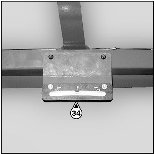
M -TRANSVERSE ATTITUDE OF THE TELESCOPIC HANDLER
The transverse (side-to-side) attitude is the angle of the chassis with respect to horizontal. Raising the boom reduces the telescopic handler's lateral stability.
Position the telescopic handler so that the bubble in the inclinometer is between the two lines (see chapter: 5 - INSTRUMENTS AND CONTROLS: 34 - INCLINOMETER).
N -PICKING UPALOAD ON THE GROUND
Approach the load with the telescopic handler perpendicular to the load, with the boom retracted and the forks in a horizontal position (fig. N1).
Adjust the fork spread and centering to best connect with the load (fig. N2).
Never lift a load on a single fork.
Move the telescopic handler forward slowly (1) and bring the forks to stop in front of the load (fig. N3). If necessary, slightly lift the boom (2) while picking up the load.
Warning
Bring the load into the transport position.
Tilt the load back far enough to ensure stability (loss of load while braking or going downhill).
FOR ANON-PALLETIZED LOAD:
Tilt the carriage (1) forward and move the telescopic handler slowly forward (2), to insert the forks under the load (fig. N4) (block the load if necessary).
Continue to move the telescopic handler forward (2) tilting the carriage (3) (fig. N4) rearward to position the load on the forks and check the load's longitudinal and lateral stability.
O -PICKING UPAHIGH LOAD
Warning
DO NOT raise the boom until you have verified the side-to-side attitude of the telescopic handler.
Make sure that the following operations can be performed with good visibility.
Ensure that the forks will easily pass under the load.
Lift and extend the boom (1) (2) until the forks are level with the load, moving the telescopic handler (3) forward if necessary (fig. O1), moving very slowly and carefully.
Always think about keeping the distance necessary to fit the forks under the load between the pile and the telescopic handler (fig. O1) and use the shortest possible extension of the boom.
Slightly lift the load (1) and tilt the carriage (2) rearward to stabilize the load (fig. O3).
Stop the forks in front of the load by alternately raising and extending the boom (1) or, if necessary, moving the telescopic handler forward (2) (fig. O2). Apply the parking brake and shift the transmission into neutral.
Tilt the load sufficiently rearward to ensure its stability.
If possible lower the load without moving the telescopic handler. Lift the boom (1) to release the load, retract (2) and lower the boom (3) to bring the load into the transport position (fig. O4).
If this is not possible, back up the telescopic handler (1), maneuvering very gently and carefully to release the load. Retract (2) and lower the boom (3) to bring the load into the transport position (fig. O5).
P-SETTING DOWN AHIGH LOAD
Approach with the load in the transport position in front of the stack (fig. P6).
If possible, release the fork by alternately retracting and raising the boom (1) (fig. P9). Then return the forks to transport position.
Apply the parking brake and set the forward/reverse lever in neutral.
Lift and extend the boom (1) (2) until the load is above the stack. If necessary, move the telescopic handler (3) forward (fig. P7), driving very slowly and carefully.
If this is not possible, reverse the telescopic handler (1) very slowly and carefully to release the forks (fig. P10). Then return the forks to transport position.
Place the load in a horizontal position and set it down on the stack by lowering and retracting the boom (1) (2) to position the load correctly (fig. P8).
Q -SUSPENDED LOADS
The handling of suspended loads by means of the truss boom or other similar device can introduce dynamic forces affecting the stability of the machine that are not considered in the stability criteria of industry test standards. Grades, sudden starts, stops and turns can cause the load to swing and create a hazard.
DO NOTexceed the Telescopic Handler capacity for handling suspended loads. Only lift the load vertically; NEVER drag it horizontally. Use tag lines to restrain load swing whenever possible.
GUIDELINES FOR “FREE RIGGING/SUSPENDED LOADS”
1.The rigging equipment must be in good condition and comply with the applicable U.S. OSHAregulation, 1910.184, “Slings,” or 1926.251, “Rigging equipment for material handling.”
2.The rigging equipment must be secured to the forks such that it cannot slip or slide either sideways or fore and aft.
3.The capacity of the fork(s) and the machine (whichever is less) must not be exceeded.
4.The load center must remain at 24” (610 mm) or less.
5.No lifting of material may be done when anyone is on the load, rigging or forks.
6.Multiple pickup points on the load are preferred to prevent the load from rotating, but a single pickup point may be used if one or more tag lines are utilized. And, of course, the load must never be positioned over personnel at any time.
Chapter 5
Instruments And Controls


Description
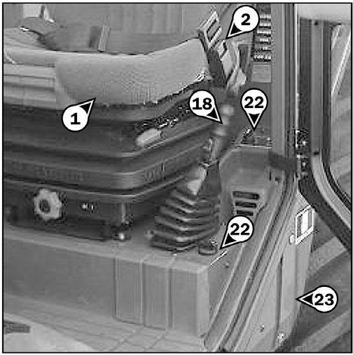
1- OPERATOR’S SEAT
2- SEATBELT
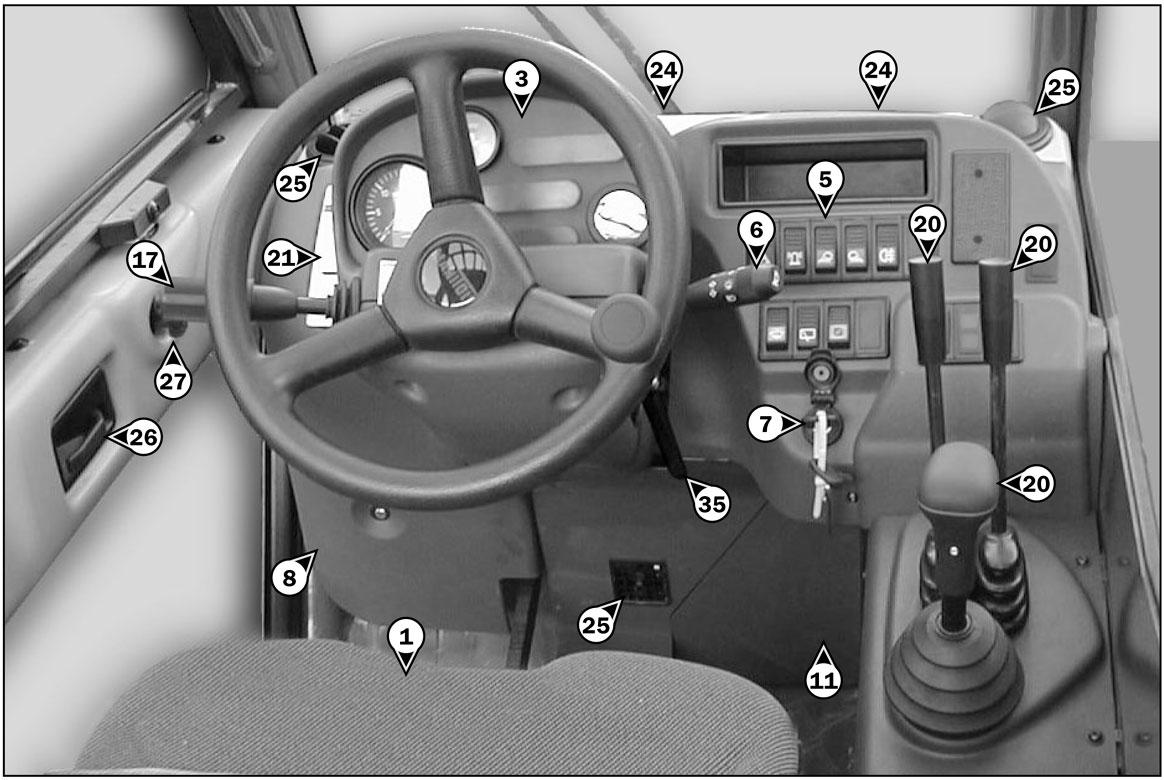
3- CONTROLAND SIGNALLAMPPANEL
4- BOOM-MOUNTED WORK LIGHTS (See page 37)
5- SWITCH PANEL
6- LIGHTSWITCH, HORN AND INDICATOR SWITCH
7- IGNITION SWITCH
8- BRAKE FLUID RESERVOIR AND WINDSHIELD WASHER TANK ACCESS PANEL
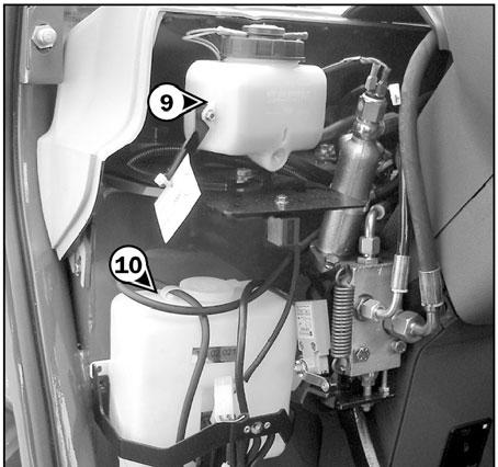
9- BRAKE FLUID RESERVOIR
10- WINDSHIELD WASHER TANK
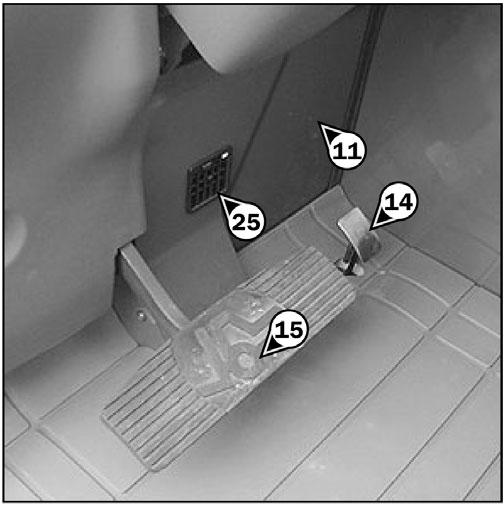
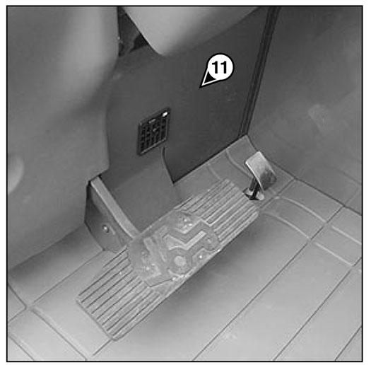
11- FUSES AND RELAYS ACCESS PANEL
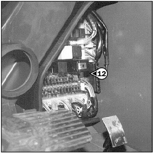
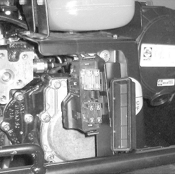
12- FUSES AND RELAYS
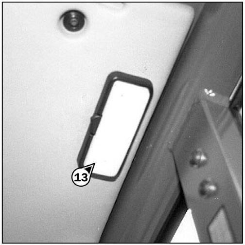
13- CAB INTERIOR LIGHT
14- ACCELERATOR PEDAL
15- SERVICE BRAKE PEDALAND TRANSMISSION CUT-OFF
16- SHIFTLEVER AND TRANSMISSION CUT-OFF
17- FORWARD/REVERSE LEVER
18- PARKING BRAKE LEVER
19- STEERING SELECTION
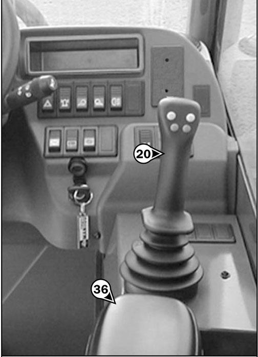
20- HYDRAULIC CONTROLS AND TRANSMISSION CUT-OFF
21- LOAD CHARTS
22- HEATER CONTROLS
- HEATER / AIR CONDITIONING CONTROLS
23- CAB AIR FILTERS
24- WINDSHIELD DEFROSTER
25- HEATING VENTS
26- DOOR LOCK
27- LOCKING HANDLE FOR UPPER HALF DOOR
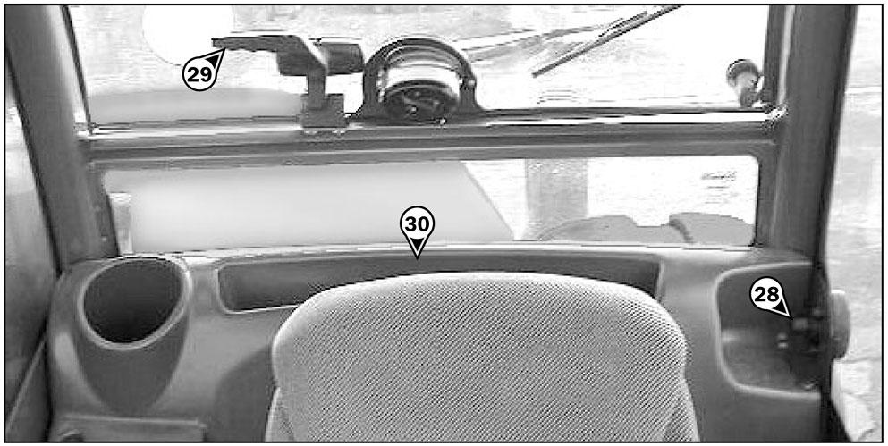
28- RELEASING BUTTON FOR UPPER HALF DOOR
29- HANDLE FOR REAR WINDOWOPENING
30- MANUALHOLDER
31- FRONTLIGHTS (See page 45)
32- REAR LIGHTS (See page 45)
33- ENGINE BLOCK HEATER (See page 45)
34- INCLINOMETER
35- STEERING WHEELREGULATING HANDLE
36- ARM REST
37- RADIO (See page 46)
TOWPIN (See page 46)
A- TOWING PIN
B - TRAILER ELECTRIC CONNECTOR
NOTE: All terms such as: RIGHT, LEFT, FRONT, REAR are meant for an observer seated in the operator’s seat and looking forward.
1 -OPERATOR’S SEAT - CT6-18
Designed for maximum comfort, this seat can be adjusted as follows:
LONGITUDINALADJUSTMENT
-Pull locking lever (1) towards the right.
-Slide the seat to the required position.
-Release the lever and be sure it returns to the lock position.
NOTE: It is recommended that the weight should be checked and adjusted before starting the telescopic handler.
Seatsuspension Adjustment
-Refer to the seat's graduation.
-Turn handle (2) depending on the operator’s weight. ADJUSTMENTOF THE ANGLE OF THE BACKREST
-Pull locking lever (3) upwards.
-Slide the back-rest to the required position.
-Release the lever and be sure it returns to the lock position.
SEATHEIGHTADJUSTMENT(FIG. B)
Raise the seat to the desired position, until you hear the ratchet click. If you raise the seat above the last notch (stop), the seat drops down to the lowest position.
1 -OPERATOR’S SEAT - CT6-18 TURBO
Designed for maximum comfort, this seat can be adjusted as follows.
WEIGHTADJUSTMENT(FIG. A)
It is recommended that the weight be adjusted when the operator is not sitting in the seat.
-Refer to graduation (1) of the seat.
-Turn handle (2) according to the operator’s weight.
SEATBACK-RESTANGLE ADJUSTMENT(FIG. C)
The back rest angle of the seat may be adjusted to suit the individual.
-Press the left-hand button while pushing on the seat or relaxing pressure on the seat to find a comfortable position.
SEATDEPTH ADJUSTMENT(FIG. D)
The depth of the seat may be adjusted to suit the individual.
-Press the right-hand button while raising or lowering the seat to find the desired position.
EXTENDING THE HEAD REST(FIG. E)
-The height of the back rest can be adjusted by pulling it upwards (the notches will click) up to the stop.
-The head rest can be removed by applying sufficient pressure to pull it off the stop.
Warning
Support the back rest when making adjustments to prevent it from swinging completely forward.
MAINTENANCE
(FIG. I)
Dirt may adversely affect the correct functioning of the seat. For this reason, make sure your seat is always clean.
LUMBAR ADJUSTMENT(FIG. F)
This increases the comfort of the seat and the operator’s freedom of movement.
-Turn the handle either left or right to adjust the height or depth of the lumbar support.
-To clean or change the cushions, simply remove them from the seat frame.
Avoid wetting the cushion fabric when cleaning. Check the resistance of the fabric on a small hidden area before using any fabric or plastic cleaner.
ADJUSTMENTOF THE ANGLE OF THE BACKREST(FIG. G)
-Support the back rest, pull the lever and position the back-rest to find the desired position.
LONGITUDINALADJUSTMENT(FIG. H)
-Adjust the locking lever until you reach the position required. This then locks and the seat will not shift into another position.
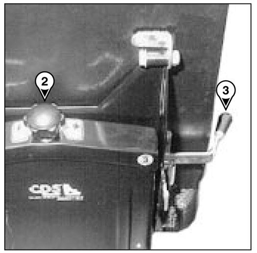
2 -SAFETYBELT
- Sit correctly on the seat.
- Check that seat belt is not twisted.
- Place the seat belt at hip level.
- Attach the seat belt and check that it latches.
- Adjust the seat belt to your body shape, without squeezing your hips and without excess slack.
Warning
Do not use the telescopic handler if the seat belt is damaged (not latching, cuts, tears, etc.). Repair or replace the seat belt immediately.
3
CONTROLINSTRUMENTS
A-HOURMETER AND TACHOMETER
CT6-18 Turbo
B4 - Red zone 221° F - 248° F (105° C - 120° C)
NOTE: Red indicator light “E” comes on between zone B3 and B4.
C -FUELLEVEL
Red zone C1 indicates that you are using the reserve supply and that time of use is limited.
SIGNALLIGHTS
When activating the electrical system of the telescopic handler, all the red lamps must light and the panel's buzzer must sound to indicate their good working order. If one of the red lamps or the buzzer does not function, carry out the necessary repairs.
A-HOURMETER
CT6-18
B -ENGINE COOLANTTEMPERATURE
Temperature zone
B1 - Blue zone 32° F - 122° F (0° C - 50° C)
B2 - Green zone 122° F - 212° F (50° C - 100° C)
B3 - Black/red zone 212° F - 221° F (100° C - 105° C)
D -RED TRANSMISSION OILPRESSURE LAMP
The lamp and the buzzer come on when the pressure in the transmission, when driving forward, is abnormally low. Stop the telescopic handler and look for the cause (insufficient transmission oil level, internal leak in the transmission, etc.).
NOTE: The signal lamp operates in forward travel conditions only. The signal should not be taken into account when the engine is running at idle or is stopped.
E -RED TRANSMISSION OILTEMPERATURE LAMP
The lamp and the buzzer come on when the converter oil temperature is abnormally high. Stop the lift truck and look for the cause of this overheating.
F -RED BRAKE FLUID LEVELLAMP
If the lamp and the buzzer come on, when the lift truck is running, stop the engine immediately and check the brake fluid level.
In the event of an abnormal dropping of the level, consult your dealer.
G -RED PARKING BRAKE LAMP
This lamp comes on when the parking brake is applied.
H -RED ALTERNATOR CHARGE LAMP
If the lamps E - F - H - I - J - K and the buzzer come on, when the lift truck is running, stop the engine immediately and check the electrical circuit as well as the alternator belt.
I -RED ENGINE OILPRESSURE LAMP
If the lamp and the buzzer come on when the telescopic handler is running, stop the engine immediately and look for the cause (check oil level in engine crankcase).
J -RED ENGINE COOLANTTEMPERATURE LAMP
If the lamp and the buzzer come on when the telescopic handler is running, stop the engine immediately and investigate the cooling system for the cause of the malfunction.
K -RED LAMP- AIR FILTER OR HYDRAULIC RETURN FILTER CLOGGED
The lamp and buzzer come on when the air filter cartridge or the hydraulic return oil filter cartridge is clogged. Stop the telescopic handler and carry out the necessary repairs (see cleaning and replacement requirements in chapter: 6 - MAINTENANCE: FILTER CARTRIDGES AND BELTS).
L-GREEN TURN INDICATOR LAMP
M -GREEN SIDELIGHTS LAMP
N -GREEN LOWBEAM LAMP
O -BLUE MAIN BEAM LAMP
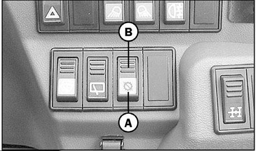
4 -BOOM-MOUNTED WORK LIGHTS (OPTION)
This switch lights the work lights mounted at the end of the boom. Pressing the bottom of the switch turns “ON” the boom work lights.
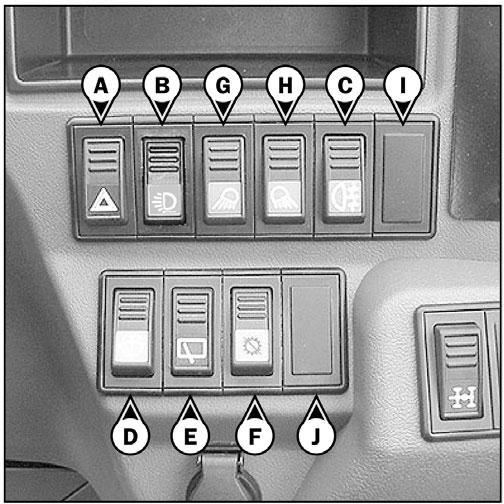
C -REAR FOG LIGHT
D -FRONTWINDSHIELD WIPER AND WINDSHIELD WASHER
Pressing the bottom of this switch to the first position operates the windshield wiper. Further pressing and holding the bottom of the switch simultaneously operates the windshield wiper and windshield washer.
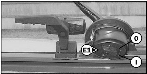
E -REAR WINDSHIELD WIPER AND ROOF WINDSHIELD WIPER
Pressing the top of the switch operates the roof window wiper when equipped. Pressing and holding the bottom of the switch operates the rear windshield wiper. NOTE: The rear windshield wiper is operated with this switch only ; to do so, the switch (E1) located on the rear windshield wiper motor must be switched to the “ON” position (I).
F -TRANSMISSION CUT-OFF
The switch selects transmission cut-off to the service brake pedal or the hydraulic controls lever.
Position A: Indicator light on, transmission cut-off to service brake pedal enabled.
Position B: Indicator light off, transmission cut-off to hydraulic control lever enabled.
The location of the switches may vary depending on the options.
A-WARNING LIGHTS
This switch enables the left and right indicators to be switched on simultaneously, with the ignition off. The switch lamp indicates that the switch is being used.
B -BOOM-MOUNTED WORK LIGHTS (OPTION)
NOTE: In all cases transmission cut-off can be effected by using the shift lever.
USE OF TRANSMISSION CUT-OFF
Transmission cut-off to brake pedal (position A):
•When loading.
Transmision cut-off to hydraulic controls lever (position B):
•When driving
•For inching and continuous stopping and starting (delicate handling) (In order to optimise hydraulic movements, cut off transmission to the hydraulic controls lever).
•Starting up on a slope
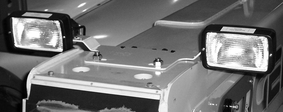
G -FRONTWORKING LIGHT (OPTION for CT6-18)
Pressing the bottom of this switch turns “ON” the front work lights located on the top front of the cab.
H -REAR WORKING LIGHT (OPTION for CT6-18)
Pressing the bottom of this switch turns “ON” the rear work light located on the top rear of the cab.
I -OPTION
J -OPTION
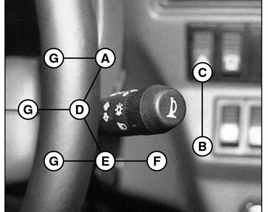
6 -LIGHT SWITCH, HORN AND INDICATOR SWITCH
The switch controls the visual and audible alarms.
A-All lights are off; the direction indicators do not flash.
B -The right turn indicators flash.
C -The left turn indicators flash.
D -The sidelights and the rear lights are on.
E -The low-beam headlights and the rear lights are on.
F -The high-beam headlights and the rear lights are on.
G -Flashes high-beam headlights when held in this position.
Pressing the switch sounds the horn.
NOTE: The positions D - E - F- G can be used without the ignition being on.
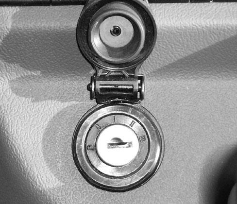
7 -IGNITION SWITCH
The key switch has five positions:
P-Ignition off, parking position
O -Ignition switched off and engine stopped
I -Ignition on
II -Pre-heating
III -Start
When the engine starts, return to position I as soon as the key is released
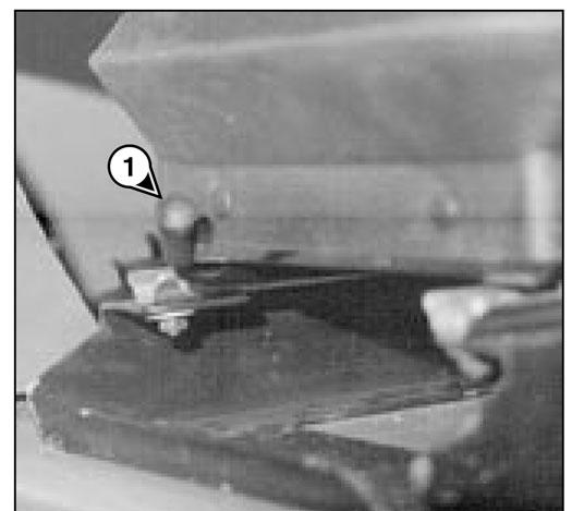
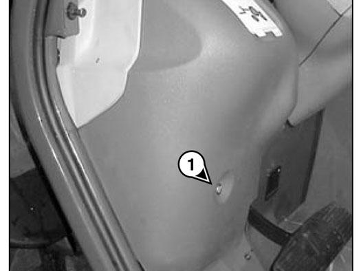
8
-Loosen screw (1) and lift up the brake fluid and windscreen washer access panel.
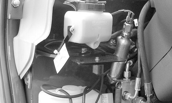
9
See chapter: 6 - MAINTENANCE: B - EVERY50 HOURS SERVICE.
10
See chapter: 6 - MAINTENANCE: B - EVERY50 HOURS SERVICE.
11 - FUSE AND RELAYACCESS PANEL
-Lift up the fuse and relay access panel 11.
12 - FUSES AND RELAYS
Asticker on the inside of the access panel gives a clear display of the use of the components described below.
K0- OPTION
K1- Relay cutting transmission to hydraulic controls (CT6-18 TURBO)
- OPTION (CT6-18)
K2- Transmission cut-off relay
K3- Reverse gear relay
K4- Forward gear relay
K5- Buzzer
K6- OPTION
K7- OPTION
K8- Safety system starting switch relay
K9- Flashing unit
K16- Preheating engine relay
K17- Control panel lighting relay
F2- (15AMAX.) -Working tail light (10A) (CT6-18 Turbo)
- Working tail light (OPTION) (10A) (CT6-18)
F3- (10AMAX.) - Rear windshield wiper (7.5A)
- Roof windshield wiper (7.5A) (CT6-18 TURBO)
- Roof windshield wiper (OPTION) (7.5A) (CT6-18)
F4- (10AMAX.) - Stop engine electrovalve (7.5A)
F5- (10AMAX.) - OPTION
F6- (7.5AMAX.) - Alignment of the wheels (5A)
F7- (15AMAX.) - OPTION
F8- (15AMAX.) - Gear reverser (15A)
- Transmission cut-off (15A)
- Reverse lights (15A)
- Reverse buzzer alarm (15A)
F9- (10AMAX.) - Control instruments panel (5A)
F10- (15AMAX.) - Sound alarm (15A)
- Stop switch (15A)
F11- (15AMAX.) - OPTION
F12- (10AMAX.) - Indicator power supply (10A)
F13- (35AMAX.) - Heating (30A)
F14- (25AMAX.) - OPTION
F15- (25AMAX.) - OPTION
NOTE: Replace a used fuse with a new fuse of the same quality and capacity. Never reuse a repaired fuse.
F1- (10AMAX.) - Electric controls of hydraulic movements (7.5A) (CT6-18 TURBO)
- OPTION (CT6-18)
F16 - (10AMAX.) - OPTION
F17 - (15AMAX.) - OPTION
F18- (15AMAX.) - Front working head light (15A) (CT6-18 TURBO)
- Front working head light (15A) (OPTION CT6-18).
F19- (15AMAX.) - OPTION
F20- (10AMAX.) - OPTION
F21- (10AMAX.) - Front windscreen wiper and windscreen washer (10A)
F22- (15AMAX.) - OPTION
F23- (10AMAX.) - Right sidelight (7.5A)
- Sidelight indicator light (7.5A)
- Control panel lighting (7.5A)
F24- (10AMAX.) - Left sidelights (7.5A)
F25- (10AMAX.) - Right indicators (7.5A)
F26- (10AMAX.) - Left indicators (7.5A)
F27- (15AMAX.) - Low beam (15A)
- Low beam indicator light (15A)
- Rear fog light (15A)
F28- (15AMAX.) - Main beam (15A)
- Main beam lamp (15A)
F29- (25AMAX.) - Hazard warning lights power supply (15A)
- Roof light (15A)
F30- (25AMAX.) - Light switch power supply, horn and indicators (25A)
F31- (20AMAX.) - Starter (20A)
Remove cap 1 for access to fuses F40 to F43
Depending on the position of the transmission cut-off switch, power to the transmission is cut off. This allows greater engine acceleration and power to the hydraulic system without power to the drive axles while the service brake pedal is depressed.. (see: chapter 5 - INSTRUMENTS AND CONTROLS: 5SWITCH PANEL).
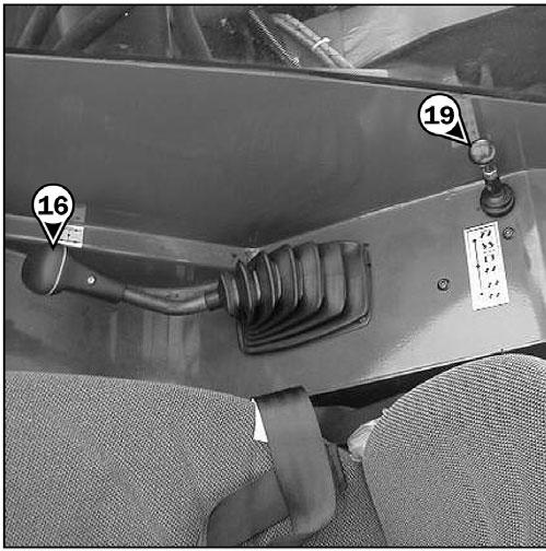
16 -SHIFT LEVER AND TRANSMISSION CUT-OFF
To shift gears, it is necessary to cut off the transmission by pressing the button (1) on the shift lever.
1st gear: To the right, upwards
2nd gear: To the right, downwards
3rd gear: To the left, upwards
4th gear: To the left, downwards
SHIFTING THE TRANSMISSION
F40- (40AMAX.) - Telescopic Handler electrical equipment (40A)
F41- (40AMAX.) - Telescopic Handler electrical equipment (40A)
F42- (80AMAX.) - Preheating engine (80A)
F43- (80AMAX.) - Alternator (80A)
13 -ROOF LIGHT
14 -ACCELERATOR PEDAL
15 -SERVICE BRAKE PEDALAND TRANSMISSION CUT-OFF
Depressing the brake pedal hydraulically activates the internal braking mechanism in the front and rear axles.
Because this telescopic handler has a torque converter, it is not necessary to always start up in 1st gear and progress up through the gears.
IMPORTANT: The choice of transmission gear should be made carefully according to the nature of the work being carried out. Apoor choice may result in an extremely rapid elevation of the transmission oil temperature through excessive slipping of the converter, which could lead to serious damage to the transmission. (It is essential to stop and change the working conditions if the transmission oil temperature indicator light comes on.) This poor choice may also result in a reduction in the telescopic handler's performance in forward speed. When the forward force increases, the forward speed in the chosen gear (for example, 3rd gear) may be lower than the forward speed that could be obtained with a lower gear (in 2nd instead of the 3rd).
In general, use the following gears according to the nature of the work being carried out:
• On the road: Start off in 3rd gear and shift up to 4th if the conditions permit. In hilly areas: Start off in 2nd gear and shift up to 3rd if the conditions permit.
• With a trailer on the road: Start in 2nd gear and shift up to 3rd if the conditions permit.
• Material handling: Start in 3rd gear, or 2nd gear in restricted spaces.
• Earthmoving: Start in 1st gear.
• Loading (with bucket, manure fork, etc.): Start in 2nd gear.
17 - FORWARD/REVERSE LEVER
This lever is used to change the direction of travel (forward or reverse).
NOTE: To prevent damage to the transmission, the telescopic handler should be traveling at a slow speed and not accelerating when changing the direction of travel.
When the forward/reverse lever is in the neutral position, a mechanical lock prevents an inadvertent shifting movement.
2 - release the parking brake, and 3 - shift into forward or reverse.
To stop the telescopic handler, the following sequence must be followed:
1 - shift into neutral,
2 - apply the parking brake, and
3 - step out of the telescopic handler.
If this sequence is not followed (for example, leaving the operator’s seat without applying the parking brake), an alarm will sound. The operator must then shift into neutral and follow the sequence.
18 - PARKING BRAKE LEVER
To prevent inadvertent release, the lever is fitted with a safety lock.
-To apply the parking brake, pull the lever rearward (position A).
-To release the parking brake, release the safety lock and push the lever forward (position B).
FORWARD: Lift slightly and push the lever forward (position A).
REVERSE: Lift slightly and pull the lever rearward (position B).
NEUTRAL: To start the engine, the lever must be in neutral (position C).
NOTE: The reverse lights and the backup alarm indicate when the telescopic handler is operating in reverse.
Procedure To Move The Telescopic Handler
The telescopic handler is equipped with an electronic unit that prevents the machine from moving unless the operator is seated in the seat.
To move the telescopic handler, the following sequence must be followed:
1 - sit in the operator’s seat,
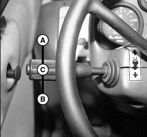
19 - STEERING MODE SELECTION
Before selecting one of the three possible steering positions, bring the four wheels into alignment, i.e., in the straight-ahead position.
A-STEERING SELECTOR LEVER
A1 -Front wheels steer (highway use)
A2 -Front and rear wheels steer in opposite direction (4-wheel steer)
A3 -Front and rear wheels steer in the same direction (crab steer)
B -GREEN LAMPS FOR ALIGNMENT OF THE WHEELS
These lamps come on to indicate the alignment of the wheels in relation to the axles of the telescopic handler. The lamp B1 is for the front wheels, and the lamp B2 is for the rear wheels.