7 minute read
D -EVERY500 HOURS SERVICE

from Gehl CT6-18 Low Profile CT6-18 Turbo Telescopic Handler Operator's Manual 913223 - PDF DOWNLOAD

Perform the operations described previously as well as the following operations:
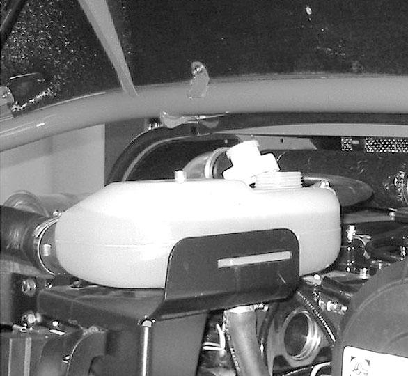
D1 -ENGINE OIL
DRAIN
D2 -ENGINE OILFILTER CHANGE
Park the telescopic handler on level ground, let the engine run at idle for a few minutes, and then stop the engine.
DRAINING THE OIL
-Open the engine cover.
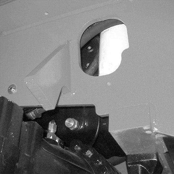
-Remove access panel (1) (fig. D1/1).
-Place a container under drain plug (2) (fig. D1/2) and unscrew the plug.

-Clean the filter mounting surface with a clean, lintfree cloth.
-Lightly grease the new oil filter seal and install the oil filter (see chapter: 6 - MAINTENANCE: FILTER CARTRIDGES AND BELTS).
IMPORTANT: Tighten the oil filter by hand, and then secure the filter with a quarter turn more.
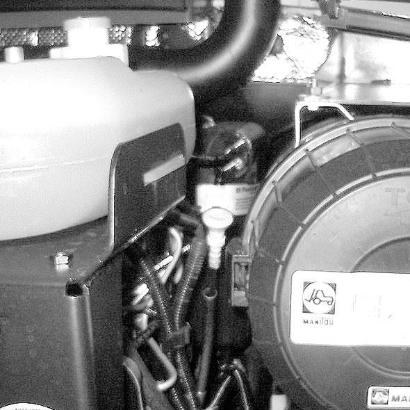
Refilling The Oil
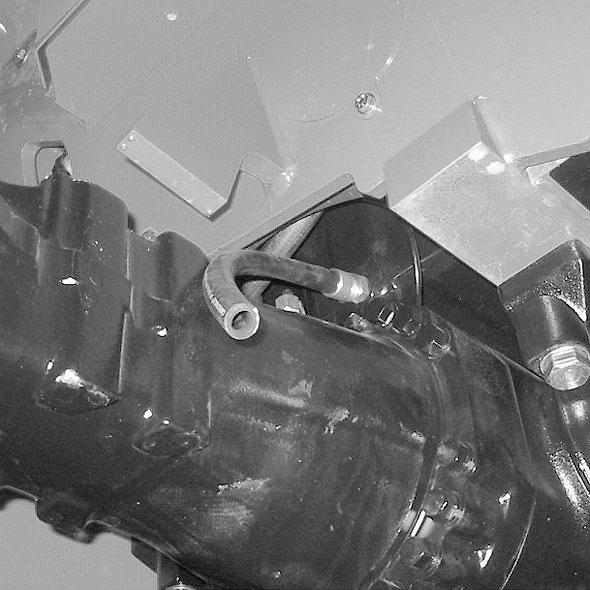
-Loosen, clean and replace the drain hose (3) (fig. D1/3).
-Replace and tighten drain plug (2) (fig. D1/2).
-Replace access panel (1) (fig. D1/1).
-Fill with oil (see chapter: 6 - MAINTENANCE: LUBRICANTAND FUEL) by filler port (7) (fig. D1/5).
-Wait a few minutes to allow the oil to flow into the crankcase.
-Start the engine and let it run for a few minutes.
-Check for possible leaks at the drain plug and the oil filter.
-Stop the engine, wait a few minutes and check that the level is at the upper mark on dipstick (8) (fig. D1/6).
-Top up if necessary.
-Take drain hose (3) (fig. D1/3).
-Screw drain hose to the draining port (4) (fig. D1/4).
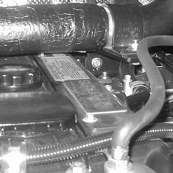
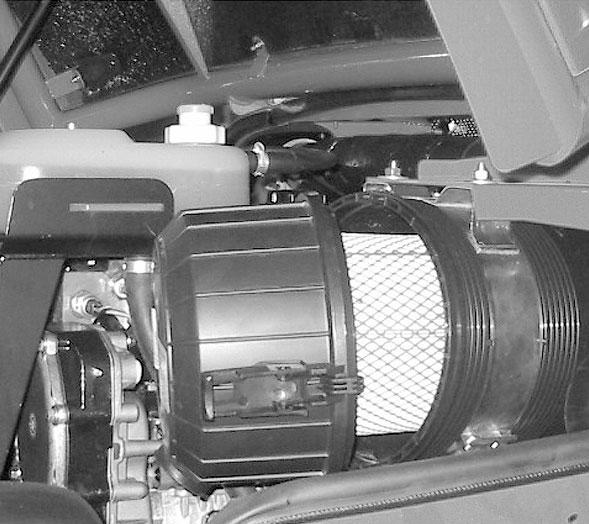
D3 -DRYAIR FILTER CARTRIDGE CHANGE
In case of use in a very dusty conditions, the checking and cleaning period of the cartridge must be reduced to 250 hours.
-Remove filler cap (5) (fig. D1/5) to ensure that the oil drains properly.
IMPORTANT: Dispose of the drain oil in an ecological manner.
REPLACING THE FILTER
-Remove engine oil filter (6) (fig. D1/2) ; discard the filter and the filter seal.
IMPORTANT: Change the cartridge in a clean location, with the engine stopped. Never run the engine with the air filter removed or damaged.
-Open the engine cover.
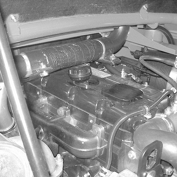
-Loosen the clips and remove cover (1) (fig. D3).
-Gently remove the cartridge (2) (fig. D3), taking care to avoid spilling the dust.
-Leave the safety cartridge in place.
-The following parts must be cleaned with a damp, clean lint-free cloth.
• The inside of the filter and cover.
• The inside of the filter inlet hose.
• The gasket surfaces on the filter and on the cover.
-Check pipes and connections between the air filter and the engine and the connection and condition of the filter indicator.
-Before installing, check the condition of the new cartridge (see chapter: 6 - MAINTENANCE: FILTER CARTRIDGES AND BELTS).
-Install the cartridge onto the filter axis and push it in, pressing the edges and not the middle.
-Reassemble the cover, with the dust valve downward.
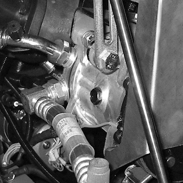
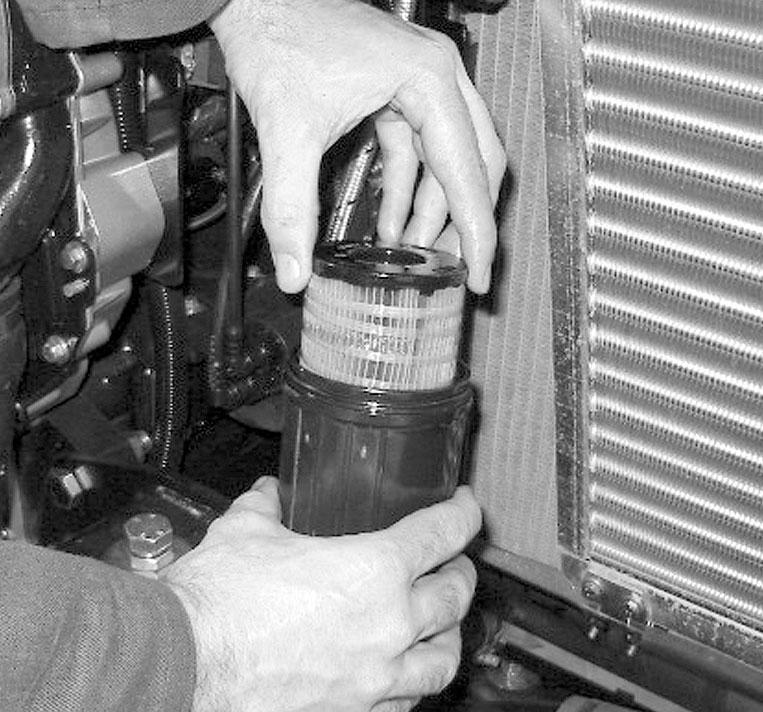
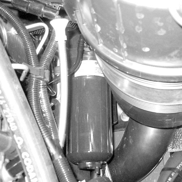
D4 -FUELFILTER CARTRIDGE CHANGE
- Open the engine cover.
-Open battery cowl.
Warning
Make sure the electrical system on the telescopic handler is disconnected, otherwise fuel will be released if the fuel pump is on.
-Carefully clean the outside of the filter and its holder, to prevent dust from getting into the fuel system.
-Place a container under the filter and drain it via drain plug (1) (fig. D4/1).
-Loosen the body of filter (2) (fig. D4/1).
-Remove the filter cartridge by pressing the cartridge (3) (fig. D4/2) down against the pressure of the spring and turn it to the left.
-Insert a new cartridge (see chapter: 6 - MAINTENANCE: FILTER CARTRIDGES AND BELTS), by pressing the cartridge (3) (fig. D4/2) down against the pressure of the spring and turning it to the right to lock it into the body of the filter.
-Place the new seal (4) (fig. D4/2) onto the body of the filter and lubricate the contact surface using clean engine oil.
-Remount the body of the filter onto its holder. Handtighten it and then secure it with a quarter turn more.
-Close drain plug (1) (fig. D4/1) and remove the container.
-Before starting the engine, leave the ignition on for one minute, to give the fuel pump time to relieve air from the filter.
-Start the engine and make sure there is no leakage.
-If necessary, bleed the fuel circuit (see chapter: 6OCCASIONALMAINTENANCE : G1 - FUEL SYSTEM).
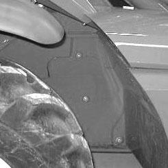
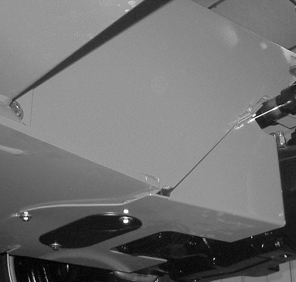
D5 -TRANSMISSION OILFILTER CHANGE
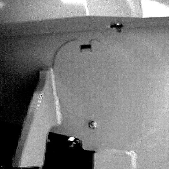
-Remove the cover plate (1) (fig. D5/1).
-Remove and discard the transmission oil filter (2) (fig. D5/2).
-Carefully clean the filter head with a clean, lint-free cloth.
-Slightly lubricate the new seal and fit the seal on the filter.
-Fill the new transmission oil filter (see chapter: 6MAINTENANCE: FILTER CARTRIDGES AND BELTS) with oil (see chapter: 6 - MAINTENANCE: LUBRICANTS AND FUEL).
-Install the filter, making sure that the seal is correctly positioned and tightened.
IMPORTANT: Tighten the transmission oil filter by hand, and then secure the filter with a quarter turn more.
-Replace the cover plate (1) (fig. D5/1).
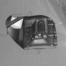
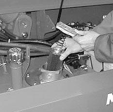
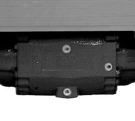
D6 -HYDRAULIC RETURN OILFILTER CARTRIDGE CHANGE
Stop the engine and relieve the pressure from the circuits by cycling the hydraulic controls.
IMPORTANT: Thoroughly clean the outside of the filter and its surroundings before servicing, to prevent contaminating the hydraulic system.
-Open the right side cover.
-Unscrew the locking screws of the cover (1) (fig. D6).
-Remove the hydraulic return oil filter cartridge (2) (fig. D6), and install a new replacement cartridge (see chapter: 6 - MAINTENANCE: FILTER CARTRIDGES AND BELTS).
-Make sure the cartridge is correctly positioned and install the cover (1) (fig. D6).
Park the telescopic handler on level ground, apply the parking brake and shift the transmission into neutral.
PURPOSE OFCOUNTER-BALANCE VALVES
-The counter-balance valves protect the user from any risk due to a sudden drop in hydraulic pressure or failed hose.
Warning
Keep everyone well away during these inspections.
In all cases, the counter-balance valve must be repaired or replaced if hydraulic movement continues after the engine has been turned off.
Never use the telescopic handler with a defective counter-balance valve.
Testingeach Hydraulic Circuit
LIFTING CIRCUIT:
-Start the telescopic handler and raise the boom to about 45°.
-With the engine running at mid-speed, lower the boom. While the boom is lowering, turn off the engine. Movement should slow as the engine speed falls and stop when the engine stops.
TELESCOPING CIRCUIT:
-Start the telescopic handler and raise the boom as far as it will go, and extend the telescopic section completely.
-With the engine running at mid-speed, retract the boom. When retracting the boom, turn off the engine. Movement should slow as the engine speed falls and stop when the engine stops.
TILTCIRCUIT:
-Place a nominal load on the forks, and anchor it securely to prevent it from falling off during the test.
-Start the telescopic handler and tilt the carriage rearward, lifting the boom sufficiently to allow the carriage to tilt.
D7 -COUNTER-BALANCE VALVE CHECK
To be performed after the first 50 hours of operation and then every 500 hours.
-With the engine running at mid-speed, tilt the carriage forward. While it is tilting, turn off the engine. Movement should slow down as the engine speed falls and stop when the engine stops.
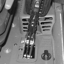
D8 -PARKING BRAKE LEVER MECHANISM
Grease
-Clean and lubricate pivot pins (1) (fig. D8) with oil (see chapter: 6 - MAINTENANCE: LUBRICANTS AND FUEL).
Warning
Handling and servicing a battery can be dangerous, take the following precautions :
- Wear protective goggles.
- Keep the battery horizontal.
- Never smoke or work near a open flame.
- Work in a well-ventilated area.
- In the event of electrolyte being spilled onto the skin or splashed in the eyes, rinse thoroughly with cold water for 15 minutes and call a doctor.
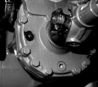
D10 -TRANSFER BOX OIL
DRAIN
D9 -BATTERYELECTROLYTE DENSITY CHECK
The electrolyte density varies depending on the temperature, but a minimum specific gravity of 1.260 at 60°F (16°C) must be maintained. In the shaded area (fig. D9), the battery is in a normal charged condition.
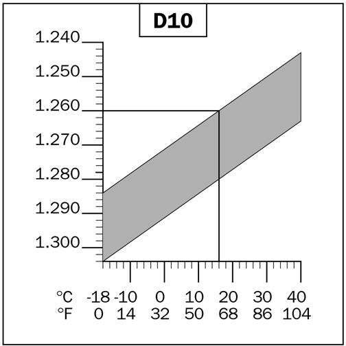
Readings above this zone indicate that the battery needs to be recharged.
-Check the electrolyte density in each battery cell using a hydrometer. The density should not vary more than 0.025 units between cells.
-Do not perform this check immediately after topping up with distilled water. Recharge the battery for at least an hour before checking the battery electrolyte density.
Park the telescopic handler on level ground with the engine stopped and the transfer box oil still warm.
IMPORTANT: Dispose of the drain oil in an ecological manner.
-Remove access panel (1) (fig. D10/1).
-Place a container under drain plug (2) (fig. D10/2) and remove the plug.
-Remove level and filler plug (3) (fig. D10/2) in order to ensure the oil is drained properly.
-Replace and tighten the drain plug (2) (fig. D10/2) [tightening torque: 25 to 36 ft.-lbs. (34 to 49 Nm)].
-Fill with oil (see chapter: 6 - MAINTENANCE: LUBRICANTS AND FUEL) by filler port 3 (fig. D10/2).
-The level is correct when the oil is flush with the edge of the level hole (3) (fig. D10/2).
-Check for any possible leaks at the drain plug.
-Replace and tighten the filler plug (2) (fig. D10/2) [tightening torque: 25 to 36 ft.-lbs. (34 to 49 Nm)].
-Replace the access panel (1) (fig. D10/1).
D11 -FRONT AND REAR AXLE DIFFERENTIALOIL
DRAIN
Park the telescopic handler on level ground with the engine stopped and the differential oil still warm.
IMPORTANT: Dispose of the drain oil in an ecological manner.
-Place a container under the drain plugs (1) (fig. D11) and unscrew the plugs.
-Remove level plug (2) (fig. D11) and filler plug 3 (fig. D11) to ensure that the oil drains properly.
-Replace and tighten drain plugs (1) (fig. D11) [tightening torque: 25 to 36 ft.-lbs. (34 to 49 Nm)].
-Fill with oil (see chapter: 6 - MAINTENANCE: LUBRICANTS AND FUEL) at filler port (3) (fig. D11).
-The level is correct when the oil level is flush with the edge of port (2) (fig. D11).
-Check for any leaks at the drain plugs.
-Replace and tighten level plug (2) (fig. D11) [tightening torque: 25 to 36 ft.-lbs. (34 to 49 Nm)] and filler plug (3) (fig. D11) [tightening torque: 25 to 36 ft.-lbs. (34 to 49 Nm)].
-Repeat this operation for the rear axle differential.