9 minute read
SERVICING SCHEDULE

from Gehl CT6-18 Low Profile CT6-18 Turbo Telescopic Handler Operator's Manual 913223 - PDF DOWNLOAD

A= ADJUSTN = CLEANAfterDay1 year1 year
C = CHECKP= BLEEDthe firstor50250oror20004000
D = DESCALER = CHANGE5010hourshours5001000hourshours
G = GREASEV = DRAINhourshourshourshours
A= ADJUSTN = CLEANAfterDay1 year1 year
C = CHECKP= BLEEDthe firstor50250oror20004000
D = DESCALER = CHANGE5010hourshours5001000hourshours
G = GREASEV = DRAINhourshourshourshours
(*) : Every 10 hours during the first 50 hours, then once at 250 hours.
(**) : Consult your dealer.
A-DAILYOR EVERY10 HOURS OF SERVICE WARNING
A1 -ENGINE OILLEVEL CHECK
Park the telescopic handler on level ground with the engine stopped, and let the oil drain into the oil pan.
-Open the engine cover.
-Remove the dipstick (1) (fig. A1).
-Wipe the dipstick and check for the correct level at the upper mark.
-If necessary, add oil (see chapter: 6 - MAINTENANCE: LUBRICANTS AND FUEL) at the filler port (2) (fig. A1).
To avoid the risk of spraying and scalding, wait until the engine has cooled down before removing the cooling system filler plug. If the coolant is very hot, add only hot coolant 176°F (80°C). In an emergency, you can use water as a coolant, and then change the coolant as soon as possible (see chapter: 6 - MAINTENANCE: F1 - COOLANT).
A3 -FUELLEVEL CHECK
Keep the fuel tank full, to reduce condensation due to atmospheric humidity.
-Open the right side cover.
-Remove cap (1) (fig. A3).
-Visually check that there is no leakage of oil from the engine.

A2 -COOLING LIQUID LEVEL CHECK
Park the telescopic handler on level ground with the engine stopped, and allow the engine to cool.
-Open the engine cover.

-Check the correct level in the middle of expansion chamber (1) (fig. A2).
-Fill the fuel tank with clean fuel (see chapter: 6MAINTENANCE: LUBRICANTS AND FUEL), filtered through a strainer or a clean, lint-free cloth, through the filler neck (2) (fig. A3).
-Replace the cap (1) (fig. A3).
-Visually check that there is no leakage from the tank and hoses.
Warning
Never smoke or have an open flame nearby during filling operations or when the tank is open.
Never refuel while the engine is running.
-If necessary, add coolant (see chapter: 6 - MAINTENANCE: LUBRICANTS AND FUEL) by the filler port (2) (fig. A2).
-Visually check that there are no leaks in the radiator and hoses.

IMPORTANT: The fuel tank is vented through the filler cap. When changing it, always use an original part, with a vent.
NOTE: Alocking fuel filler cap is available as an OPTION.
A4 -CYCLONIC PRE-FILTER CLEAN
The cleaning interval is given as a guide; however, the pre-filter must be emptied as soon as impurities reach the MAX level on the collector bowl.
-Loosen nut (1) (fig. A4), remove cover (2) (fig. A4) and empty the collector bowl.

-Clean the pre-filter unit with a clean dry cloth and re-assemble the unit.
A6 -TIRES PRESSURE AND WHEEL NUTS TORQUE CHECK
-Check the condition of the tires, to detect cuts, bulges, wear, etc.
-Check the torque of the wheel nuts.
IMPORTANT: Loose wheel nuts can cause damage and failure of the wheel bolts and distortion to the wheels.
Wheel nuts tightening torque:
• Front wheels: 465 ft.-lbs. (630 Nm) ± 15 %
• Rear wheels: 465 ft.-lbs. (630 Nm) ± 15 %
-Check and adjust the tire pressures if necessary (see chapter: 1 - SPECIFICATIONS).
Warning
IMPORTANT: When cleaning the pre-filter, take care not to let impurities into the dry air filter.
A5 -TRANSMISSION OILLEVEL CHECK

Park the telescopic handler on level ground with the boom raised, the engine stopped and cold. Check the oil level within five minutes of the engine being stopped.
-Remove the plastic cap (1) (fig. A5).
-Remove the dipstick (2) (fig. A5).
-Wipe the dipstick and check for the correct level between the MIN and MAX marks.
-If necessary, add oil (see chapter: 6 - MAINTENANCE: E3 TRANSMISSION OIL).
-Visually check that there is no leakage of oil from the transmission.
Check that the air hose is correctly connected to the tire valve before inflating. Keep everyone away during inflation. Follow the recommended tire pressures.
Warning
Inflating or servicing tires can be hazardous. Whenever possible, only trained personnel should service and mount tires. To avoid possible death or serious injury, follow the safety precautions below:
1.Be sure the rim is clean and free of rust.
2.Lubricate both the tire beads and rim flanges with a soap solution. DO NOT use oil or grease.
3.DO NOT place your fingers on the tire bead or rim during inflation. Use a clip-on tire chuck with a remote hose and gauge, which allows you to stand clear of the tire while inflating it.
4. NEVER inflate beyond 35 psi (240 kPa) to seat the beads. If the beads have not seated by the time the pressure reaches 35 psi (240 kPa), deflate the assembly, reposition the tire on the rim, relubricate both parts and re-inflate. Inflation pressure beyond 35 psi (240 kPa) with unseated beads may break the bead or rim with explosive force sufficient to cause death or serious injury.
5.After seating the beads, adjust the inflation pressure to the recommended operating pressure listed.
6.DO NOT weld, braze, or otherwise attempt to repair and use a damaged rim.
A7 -BOOM WEAR PADS CLEAN - GREASE
To be carried out every 10 hours during the first 50 hours service, then once at 250 hours.
-Extend the boom completely.

-With a brush, apply a coat of grease (see chapter: 6 - MAINTENANCE: LUBRICANTS AND FUEL) on the four sides of the telescoping sections (fig. A7).
Agradual or sudden increase in the no-load friction (cable disconnected at both ends) of a control cable is an indication of an impending or present performance problem. The control cable should be replaced.
Agradual or sudden decrease in the useable travel is a indication of an impending or present performance problem. The cable should be replaced.
Control cables that have moisture inside of them and/or have frozen should be replaced. Do not apply heat to thaw or dry control cables.
Control cable are lubricated for the life of the control cable. Do not remove the seals or lubricate the control cable.
Control cables are designed to be nonrepairable. Do not attempt to repair control cables.
Failure to heed could result in death or serious injury.
-Telescope the boom several times in order to spread the grease evenly.
-Remove any excess grease.
IMPORTANT: If the telescopic handler is used in an abrasive environment (dust, sand, coal…), use lubricating oil instead. Consult your dealer.
A8 -GENERALMACHINE OPERATION AND CONDITION CHECK
Are any decals missing or damaged? Are all guards, shields and covers in place? Do all controls function smoothly and properly? Are there any abnormal vibrations or noises? Are any hose or fitting connections leaking? Is the engine exhaust color normal?
Warning
Manufacturers of push-pull control cables advise taking the following operation and maintenance precautions:
Do not adjust the control cable with the engine running.
B -EVERY50 HOURS OF SERVICE
Perform the operations described previously as well as the following operations:
B1 -DRYAIR FILTER CARTRIDGE CHECK - CLEAN
In case of use in a very dusty atmosphere, there are pre-filtration cartridges (see chapter: 6 - MAINTENANCE: FILTER CARTRIDGES AND BELTS). Also, the checking and cleaning period of the cartridge must be reduced.
IMPORTANT: If the clogged filter indicator light comes on, this operation must be carried out as quickly as possible (1 hour maximum). The cartridge must not be cleaned more than seven times, after which the cartridge must be changed.
-For the disassembly and reassembly of the cartridge, see chapter: 6 - MAINTENANCE: D3 - DRYAIR FILTER CARTRIDGE.
-Clean the filter cartridge using a compressed air jet (max. pressure 30 psi (2 bar) directed from the top to the bottom and from the inside toward the outside at a minimum distance of 1 inch (25 mm) from the cartridge wall.
-Cleaning is completed when there is no more dust on the cartridge.
IMPORTANT: Keep the safe distance of 1 inch (25 mm) between the air jet and the cartridge to avoid tearing or making a hole in the cartridge. The cartridge must not be blown out near the air filter box. Never clean the cartridge by tapping it against a hard surface. (Protect your eyes during this procedure.)
-Clean the cartridge seal surfaces with a damp, clean lint-free cloth and grease with a silicone lubricant.
-Visually check the outer condition of the air filter and its mounts. Also verify the condition of the hoses and their connections.
IMPORTANT: Do not clean the dry air filter cartridge by washing it. Do not clean the safety cartridge located inside the filter cartridge. Instead, replace it if it is dirty or damaged.
B2 -RADIATOR CORE CLEAN
IMPORTANT: In a dirty atmosphere, clean the radiator every day. Do not use a water jet or highpressure steam, because this could damage the radiator fins.
-Open the engine cover.
-In order to prevent the radiator becoming clogged, clean the radiator with a compressed air jet directed from inside to outside. This is the only way to clean the core of debris.

-If necessary, clean the screen on the engine cover.
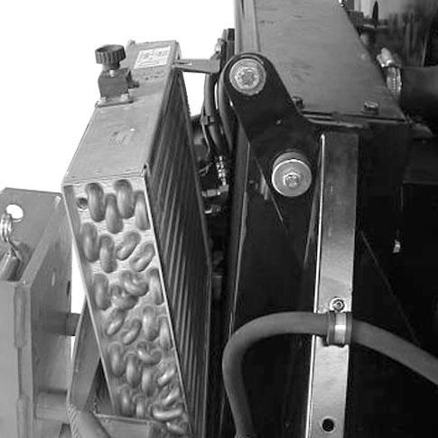
B3 -AIR CONDITIONING CONDENSER CORE CLEAN
IMPORTANT: In a dirty atmosphere, clean the condenser core every day. Do not use a water jet or high-pressure steam, because this could damage the fins.
-Open the engine cover.
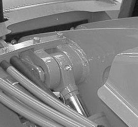
-Loosen the knurled screw (1) (fig. B3/1) and swing out the filter and condenser unit.
-Clean the core with a blast of compressed air aimed from the inside toward the outside (fig. B3/2). This is the only effective way of cleaning the core.
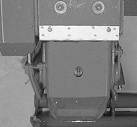
B4 -BOOM GREASE
To be performed weekly, even if the telescopic handler has been operated for less than 50 hours during the week.
IMPORTANT: In the event of prolonged use in an extremely dusty or caustic atmosphere, reduce the service interval to 10 working hours or daily.
Clean and lubricate the following points with grease (see chapter: 6 - MAINTENANCE: LUBRICANTS AND FUEL). Remove any excess grease.
-Grease fittings for the boom pivot shaft (1) (fig. B4/1).
-Grease fittings of the carriage pivot (2) (fig. B4/2).

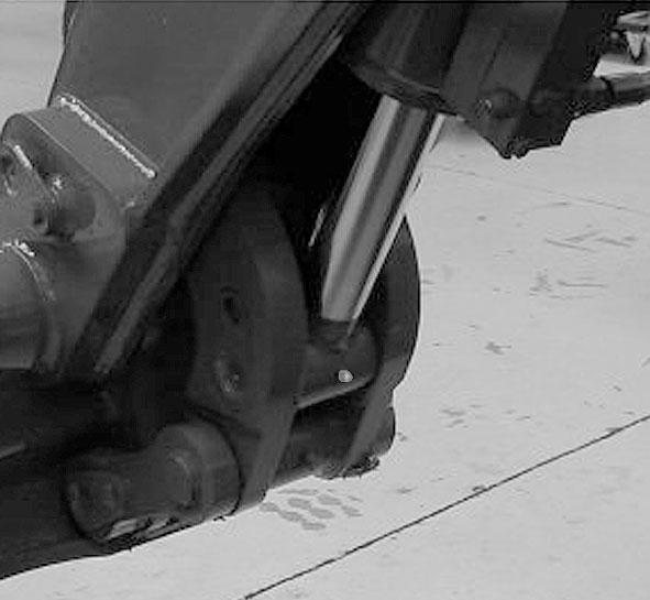
-Grease fitting for the tilt cylinder base end (1) (fig. B4/3).
-Grease fitting for the tilt cylinder rod end (1) (fig. B4/4).
-Grease fittings for the carriage connecting rod shaft (2) (fig. B4/5).
-Grease fitting for the lift cylinder base end (1) (fig. B4/6).
-Replace the cap.
-Visually check that there is no leakage from the reservoir and pipes.
Always maintain the oil level at the maximum, because cooling depends on oil flowing through the reservoir.
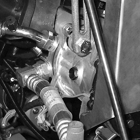
B6 -BRAKE OILLEVEL CHECK
Park the telescopic handler on level ground.
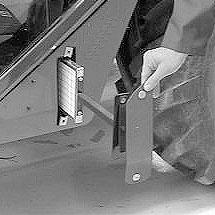
-Loosen screw (1) (fig. B6/1) and remove the access panel for the brake fluid reservoir and windshield washer tank (2) (fig. B6/1).

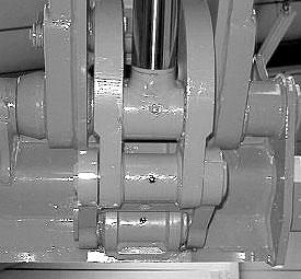
-Grease fitting for the lifting cylinder rod end (1) (fig. B4/7).
-Grease fitting for the slave cylinder base end (1) (fig. B4/6).
-Grease fitting for the slave cylinder rod end (1) (fig. B4/8).
-The level is correct when it is at the MAX level on the reservoir.
-If necessary, add oil (see chapter: 6 - MAINTENANCE: LUBRICANTS AND FUEL) at the filler neck (3) (fig. B6/2).


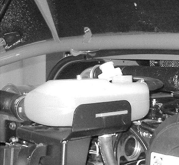
B5 -HYDRAULIC OILLEVEL CHECK
Park the telescopic handler on level ground with the engine stopped, and the boom retracted and lowered as far as possible.
-Refer to sight gauge (1) (fig. B5/1).
-The oil level is correct when it is at the level of the red point.
-If necessary, add oil (see chapter: 6 - MAINTENANCE: LUBRICANTS AND FUEL).
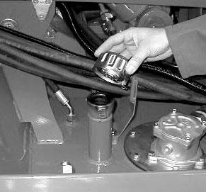
-Open the right side cover.
-Remove filler cap (2) (fig. B5/2).
-Add oil at filler neck (3) (fig. B5/2).

-Visually check that there is no leakage at the reservoir and connections.
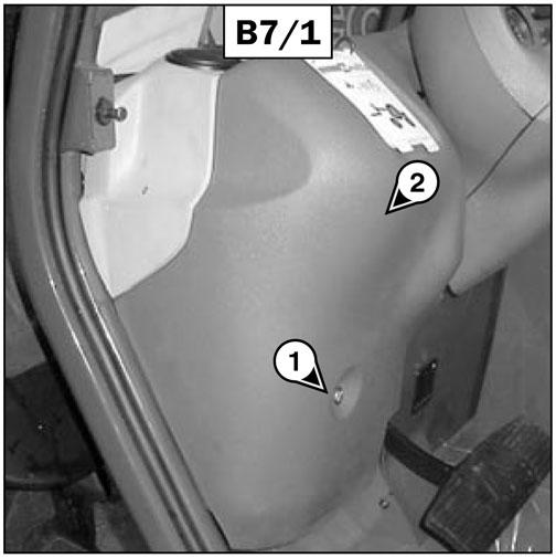
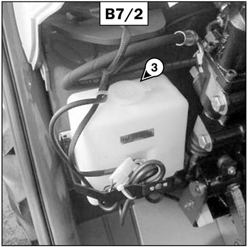
B7 -WINDSHIELD WASHER FLUID LEVEL CHECK
-Loosen screw (1) (fig. B7/1) and remove the access panel for brake fluid reservoir and windshield washer tank (2) (fig. B7/1).
-Visually check the level.
-If necessary, add windshield washer fluid (see chapter: 6 - MAINTENANCE: LUBRICANTS AND FUEL) at filler neck (3) (fig. B7/2).
B8 - CAB DOOR GREASE
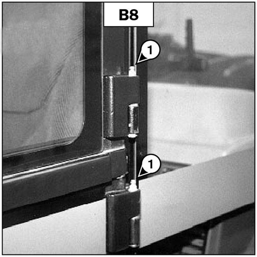
Clean and lubricate the points (1) (four fittings) (fig. B8) with grease (see chapter: 6 - MAINTENANCE: LUBRICANTS AND FUEL). Remove any excess grease.
B9 - CAB VENTILATION FILTER CLEAN
-Remove access cover (1) (fig. B9).
-Slide out cabin ventilation filter (2) (fig. B9).
-Clean the filter with a compressed air jet.
-Check its condition and change if necessary (see chapter: 5 - MAINTENANCE: FILTER CARTRIDGES AND BELTS).

-Re-install the filter and access cover.
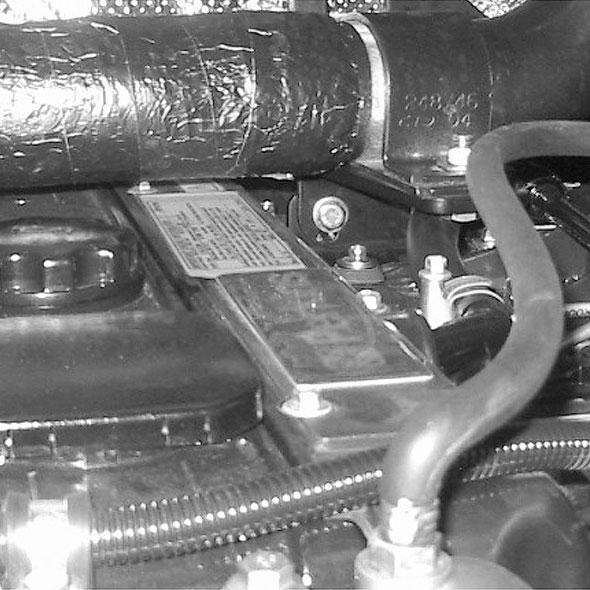
B10 -BATTERYELECTROLYTE LEVEL CHECK
Check the electrolyte level in each cell of the battery. NOTE: If the telescopic handler is working in a high temperature environment, check the level more frequently than every 50 hours of service.
-Open the right side cover.
-Remove caps (1) (fig. B10) from each cell of the battery.
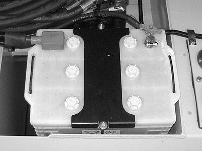
-The level is correct when it is 1/2” (13 mm) above the top of the plates in the battery.
-If necessary, top up the cells with clean distilled water that has been stored in a glass container.
-Clean and dry caps (1) (fig. B10) and replace and tighten.
-Check the terminal connections and lightly coat them with petroleum jelly to prevent corrosion.
Warning
Handling and servicing a battery can be hazarous. Take the following precautions:
-Wear protective goggles.
-Keep the battery horizontal.
-Never smoke or work near an open flame.
-Work in a well-ventilated area.
-In the event of electrolyte being spilled onto the skin or splashed in the eyes, rinse thoroughly with cold water for 15 minutes and call a doctor.
B11 -FRONT AND REAR AXLE SPINDLES
GREASE
Clean and lubricate the points (1) (eight fittings) (fig. B11) with grease (see chapter: 6 - MAINTENANCE: LUBRICANTS AND FUEL). Remove excess grease.
B12 -REAR AXLE OSCILLATION
GREASE
Clean and lubricate the points (1) (two fittings) (fig. B12) with grease (see chapter: 6 - MAINTENANCE: LUBRICANTS AND FUEL). Remove any excess grease.