3 minute read
C -EVERY250 HOURS OF SERVICE

from Gehl CT6-18 Low Profile CT6-18 Turbo Telescopic Handler Operator's Manual 913223 - PDF DOWNLOAD
Perform the operations described previously as well as the following operations:
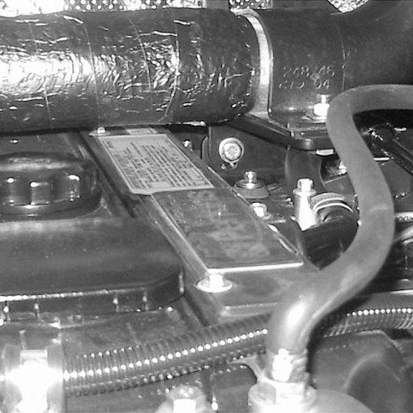
C1 -FANBELT TENSION CHECK - ADJUST
-Open the engine cover.
-Unscrew the fastening screws (1) (fig. C1/1).
-Remove the protective guard (2) (fig. C1/1).
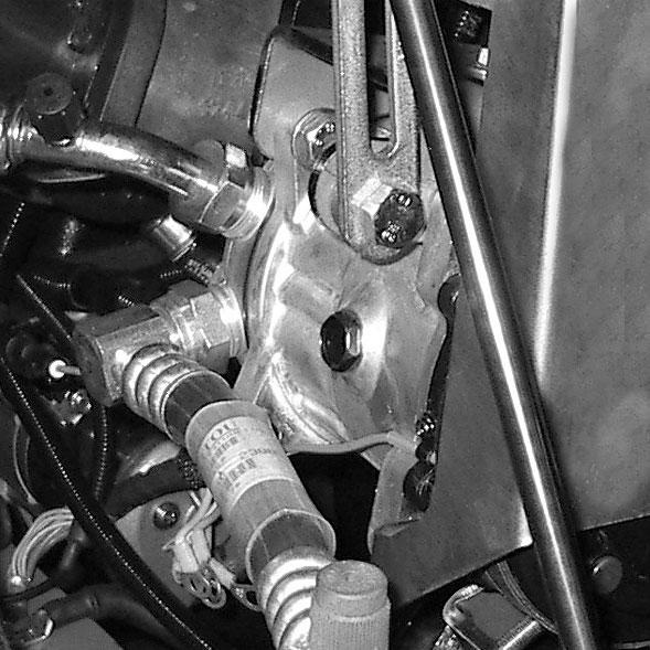
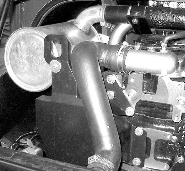
C2 -COMPRESSOR BELTS TENSION CHECK - ADJUST
-Open the engine cover.
-Unscrew the fastening screws (1) (fig. C2/1).
-Remove the protective guard (2) (fig. C2/1).
-Check the belt for signs of wear and cracks, and change if necessary (see chapter: 6 - MAINTENANCE: FILTER CARTRIDGES AND BELTS).
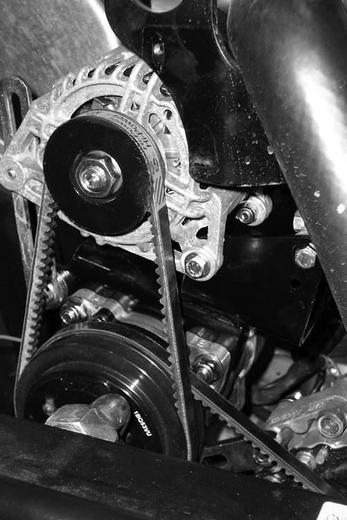
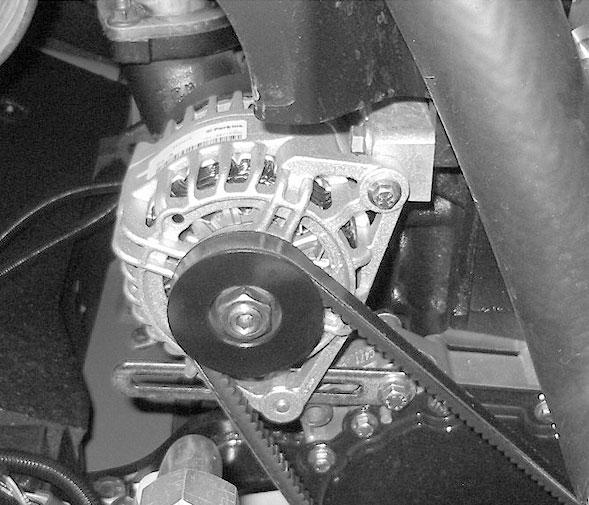
-Check the belt tension between the crankshaft pulley and the alternator pulley.
-Under a normal pressure exerted with the thumb 10 lbf. (45N), the tension should be approximately 3/8” (10 mm).
-Adjustment if necessary: a.Loosen screws (3) (fig. C1/2) by two to three turns. b.Pivot the alternator assembly to obtain the belt tension required. c.Retighten screws (3) (fig. C1/2) to a torque of 16 ft.-lbs. (22 Nm).
-Replace the protective guard (2) (fig. C1/1).
-Check the belts for signs of wear and cracks and change if necessary (see chapter: 3 - MAINTENANCE: FILTERS CARTRIDGES AND BELTS).
FAN TO COMPRESSOR BELT
-Check the belt tension between the fan pulley and the compressor pulley.
-Under normal pressure exerted with the thumb of 10 lbf. (45N), the movement should be approximately 3/8” (10 mm).
-Adjustment if necessary: a.Loosen screws (3) (fig. C2/2) two to three turns. b.Pivot the compressor assembly to obtain the belt tension required. c.Retighten screws (3) (fig. C2/2).
COMPRESSOR TO ALTERNATOR BELT
-Check the belt tension between the compressor pulley and of the alternator pulley.
-Under normal pressure exerted with the thumb of 10 lbf. (45N), the movement should be approximately 3/8” (10 mm).
-Adjustment if necessary: a.Loosen screws (4) (fig. C2/2) two to three turns. b.Pivot the alternator assembly to obtain the belt tension required. c.Retighten screws (4) (fig. C2/2).
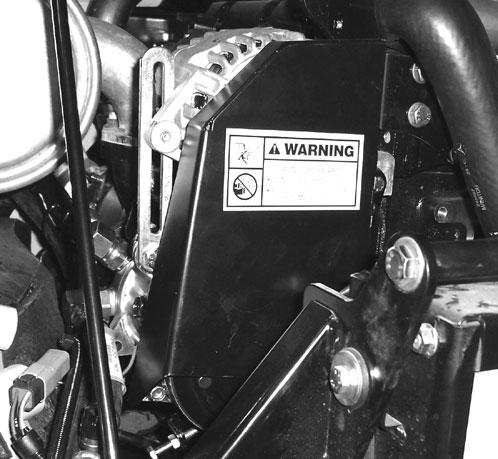
-Replace the protective guard 2 (fig. C2/1).
NOTE: If the compressor belt is changed, check the tension again after 20 hours of operation.
NOTE: If the alternator belt is changed, check the tension again after 20 hours of operation.
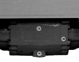
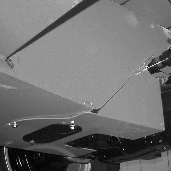
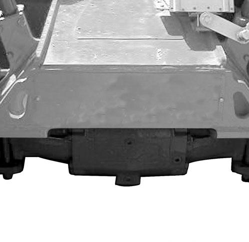
C3 -TRANSFER BOX OILLEVEL CHECK
Park the telescopic handler on level ground with the engine stopped.
-Remove access panel (1) (fig. C3/1).
-Remove the cover plate (1) (fig. C4/2).
-Unscrew nuts (2) (fig. C4/3).
-Adjust the cable by loosening nuts (2) (fig. C4/3), until a clearance of 1/16” (1.5 mm) between cams (3) (fig. C4/3) and stops (4) (fig. C4/3) is obtained.
-Remove level plug (1) (fig. C3/2). The oil should be flush with the edge of the filler port.
Warning
The adjustment of the stops performed by the manufacturer must not be modified under any circumstances.
-If necessary, add oil (see chapter: 6 - MAINTENANCE: D11 - TRANSFER BOX OIL) by the same filler port.
-Replace and tighten the level plug (1) (fig. C3/2) 25 to 36 ft.-lb. (34 to 49 Nm) tightening torque.
C4 -PARKING BRAKE CHECK - ADJUST
Park the telescopic handler on a slope of less than 15% with the rated load in the transport position.
-Check the tightening adjustment by applying the parking brake in position A(fig. C4/1).

-The adjustment is correct if the telescopic handler is held stationary on a slope.
-Adjust if necessary.
Adjustmentof The Parking Brake Cable On The Frontaxle
-Press and release the brake pedal, then release the parking brake, by putting it in position B (fig. C4/1).
Adjustmentof The Parking Brake
-Leave the parking brake in position B (fig. C4/1).
-Progressively tighten the end piece of the lever (5) (fig. C3/1) and recheck braking.
-Repeat the operation until the correct braking adjustment is obtained.
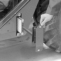
C5 -CAB VENTILATION FILTER CHANGE
-Remove access cover (1) (fig. C5).
-Slide out cab ventilation filter (2) (fig. C5) and replace with new filter (see chapter: 6 - MAINTENANCE: FILTER CARTRIDGES AND BELTS).
-Re-install the filter and access cover.
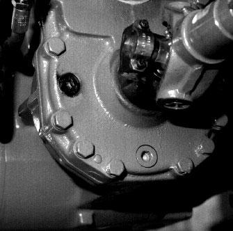
C6 -FRONT AND REAR AXLE DIFFERENTIALOILLEVEL CHECK
Park the telescopic handler on level ground with the engine stopped.
-Remove level plug (1) (fig. C6). The oil should be flush with the edge of the hole.
-If necessary, add oil (see chapter: 6 - MAINTENANCE: LUBRICANTS AND FUEL) at the filler port (2) (fig. C6).
-Replace and tighten the level plug (1) (fig. C6) [tightening torque: 25 to 36 lbs.-ft. (34 to 49 Nm)].
C7 -FRONT AND REAR AXLE PLANETARIES OILLEVEL CHECK
Park the telescopic handler on level ground with the engine stopped.
-Check the level on both front axle planetaries.
-Place level plug (1) (fig. C7) in the horizontal position.
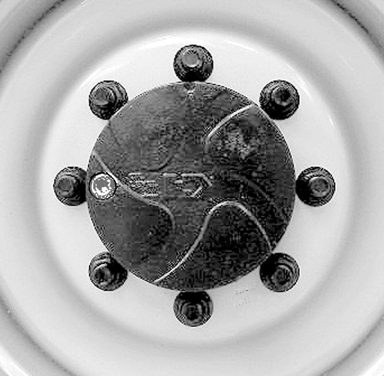
-Remove the level plug; the oil should be flush with the edge of the hole.
-If necessary, add oil (see chapter: 6 - MAINTENANCE: LUBRICANTS AND FUEL) through the same hole.
-Replace and tighten the level plug (1) (fig. C7) [tightening torque: 25 to 36 lbs.-ft. (34 to 49 Nm)].
-Repeat this operation for both differentials.