INSTALLING ATTACHMENTS
REMOVING AN ATTACHMENT - Proceed in the reverse order of paragraph INSTALLING AN ATTACHMENT. Be sure to place the attachment flat on the ground and in a closed position.
A - ATTACHMENT WITHOUT HYDRAULICS AND MANUAL LOCKING DEVICE
B - ATTACHMENT WITHOUT HYDRAULICS AND WITH HYDRAULIC LOCKING DEVICE
CT6-18 INSTALLING AN ATTACHMENT - Ensure that the attachment is in a position for locking it to the carriage. If it is not correctly oriented, take the necessary precautions to safely position it. - Check that the locking pin and the clip are in position in the bracket (fig. A). - Park the telescopic handler with the boom lowered in front of and in line with the attachment. Tilt the carriage forwards (fig. B). A
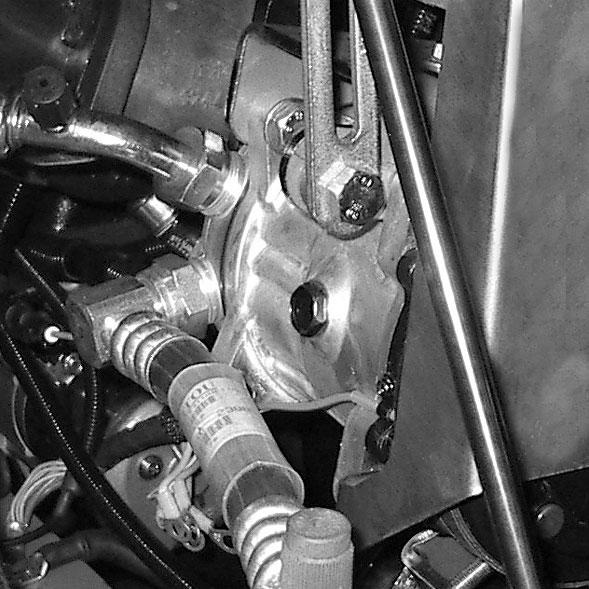
CT6-18 TURBO INSTALLING AN ATTACHMENT - Ensure that the attachment is in a position for locking it to the carriage. If it is not correctly oriented, take the necessary precautions to safely position it. - Check that the pins (1) on the locking cylinder are retracted (fig. A). - Park the telescopic handler with the boom lowered in front of and in line with the attachment. Tilt the carriage forward (fig. B).
B
A
1
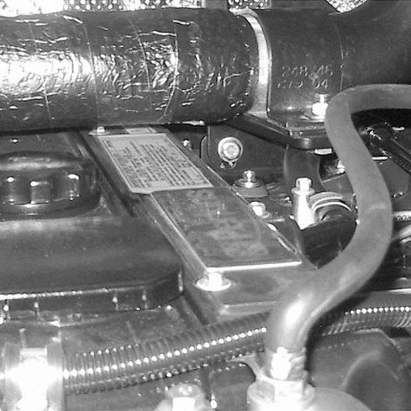
- Bring the carriage under the mounting tube of the attachment, slightly lift the boom, and tilt the carriage rearward to position the attachment (fig. C). - Lift the attachment off the ground to ease locking. MANUAL LOCKING - Remove the locking pin and the clip from the bracket (fig. A) and lock on the attachment (fig. D). Do not forget to replace the clip. C
1
- Bring the carriage under the locking tube of the attachment, slightly lift the boom, and tilt the carriage rearward to position the attachment (fig. C). - Lift the attachment off the ground to ease locking. C
D
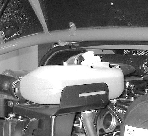
HYDRAULIC LOCKING - Place the selector valve in position A (fig. D), with the hydraulic circuit for attachment locking “open.” - Switch button (1) (fig. E) of the hydraulic control valve joystick up to lock the attachment on the carriage. - Close the valve to position B (fig. D), with the hydraulic circuit for attachment locking “closed.”
MANUAL RELEASING - Proceed in the reverse order of paragraph MANUAL LOCKING. Be sure to reinstall the locking pin and the clip in the bracket (fig. A).
PRINTED IN U.S.A.
B
81
913223/BP0206