CHAPTER 15 OPTIONAL FEATURES & AC CESSORIES GENERAL INFORMATION
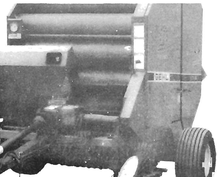
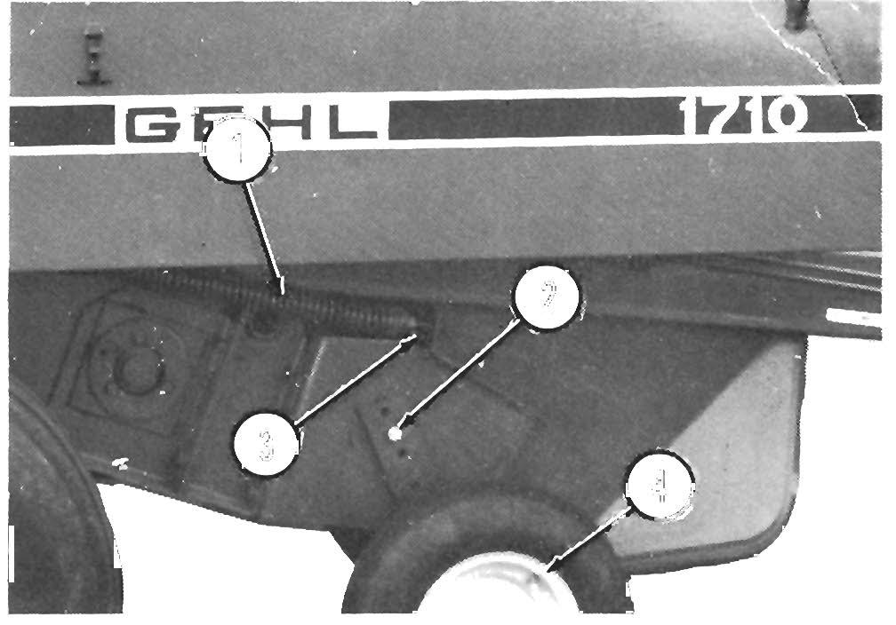
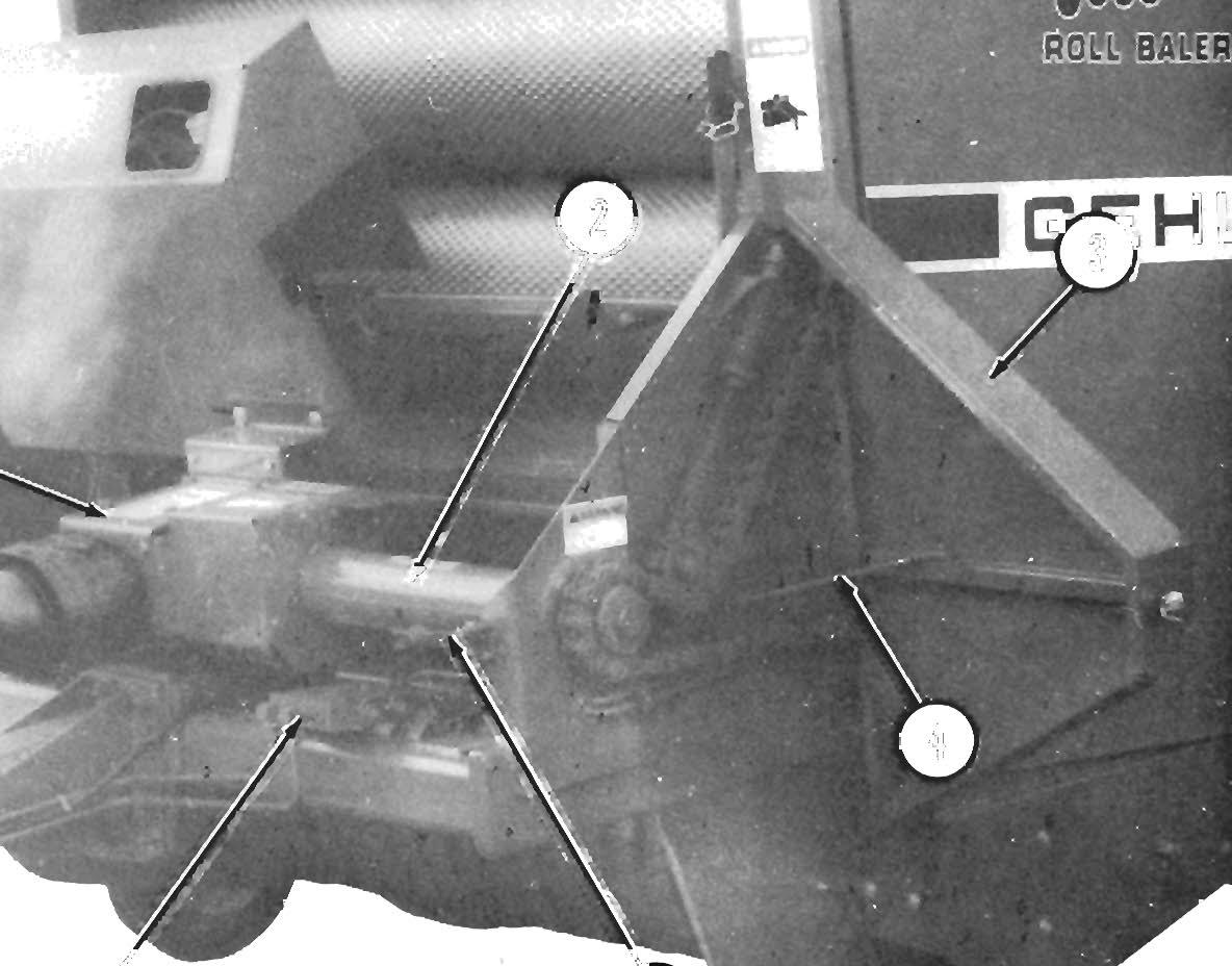
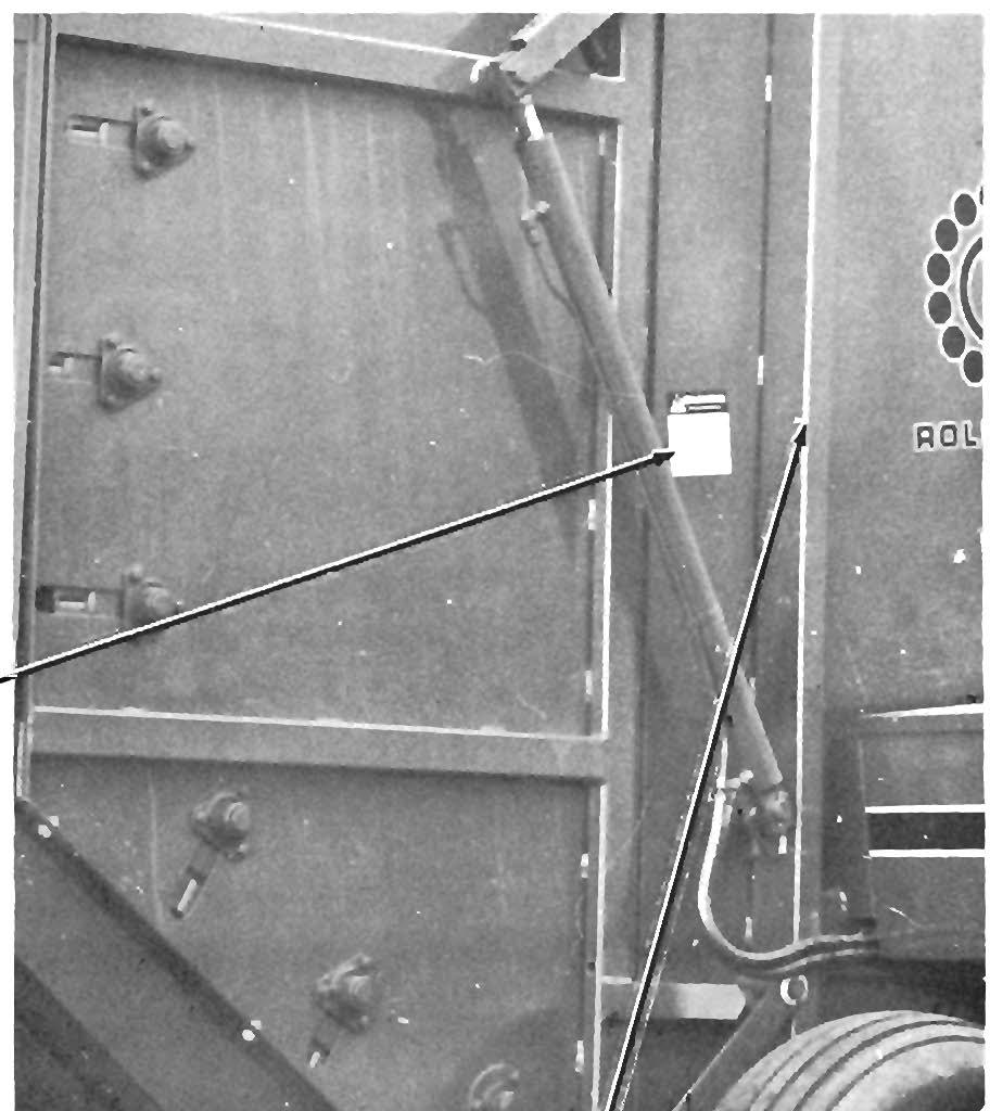
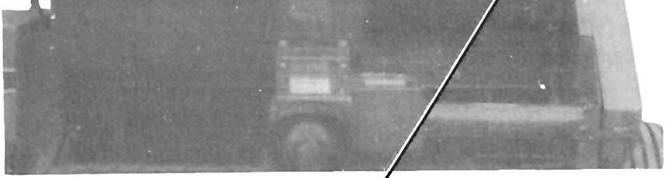
BALE DISCHARGE BUMPER (Fig. 15-2)
The following Optional Features & Accessories are available for installation on a Baler to increase is capabilities. Set-up and assembly information for all Kits, except the Twine Tie Mechanisms, are provided in separate instructions packaged with each Kit of parts.
The Bale Bumper (803643) is designed to roll the discharged bale back away from the Baler about 10 feet (3 meters) on level ground. This usually provides enough clearance to close the Rear Door without having to move the tractor forward. Installation in structions and mounting hardware are provided with the Bale Bumper.
AUTO-ELECTRIC TIE SYSTEM The Auto-Electric Wrap System .(805435) includes a tractor-mounted Control Unit, remotely mounted Sen sors, Power and interconnecting Cables, mounting Brackets and attaching hardware. Details for adapta tion and operation of the system are included in a appropriate section of this manual. The Auto-Electric Wrap System is designed to enable automatic and uniform wrapping of the bale with twine ..
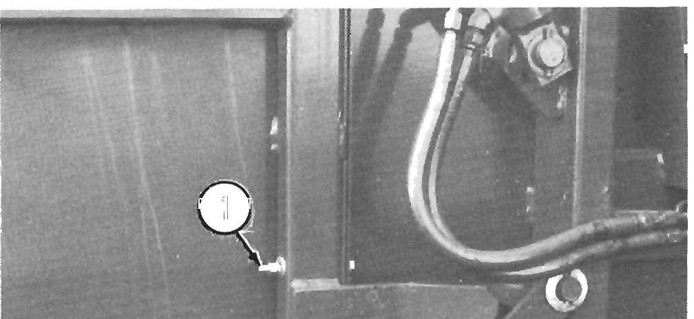
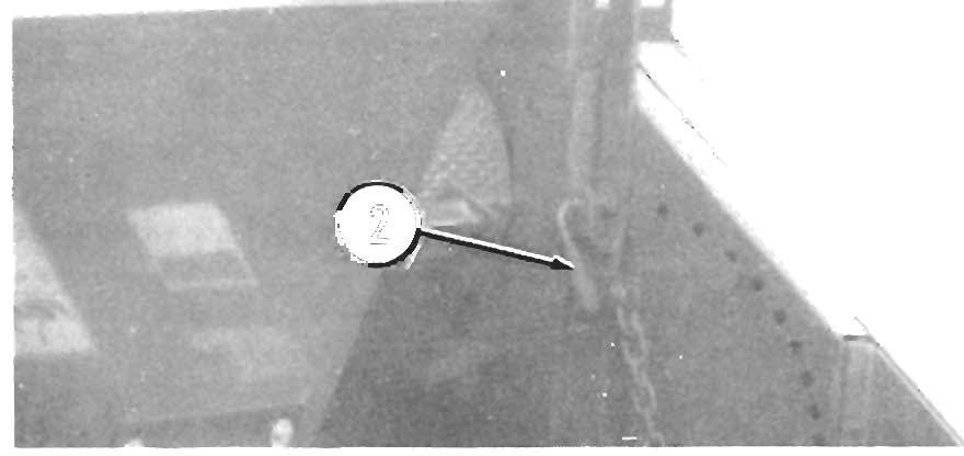
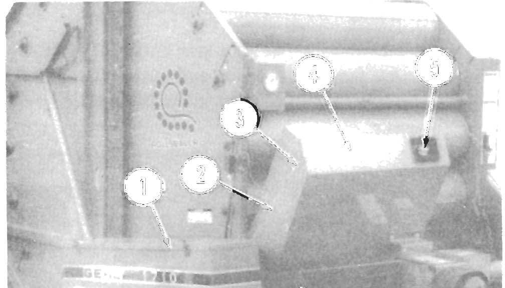
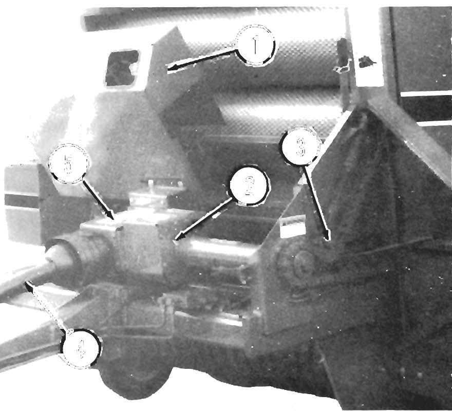
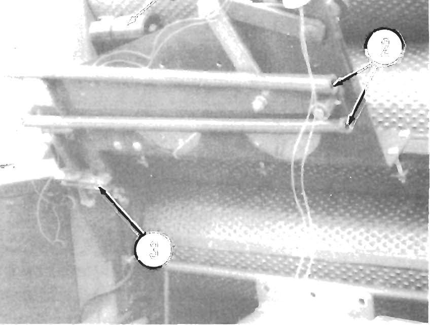
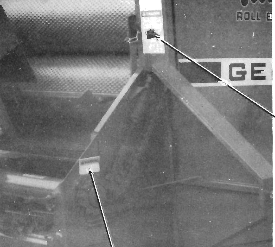
AUTOMATIC CHAiN OILER (Fig. 15-1) The Automatic Chain Oiler (803642) provides a squirt of lubrication to all of the Drive Chains (except for the Pickup Drive Chain, as noted below) every time the Rear Door opens to discharge a bale. In this way, the Chains are oiled in direct proportion to the number of bales produced. Installation details are included with the Chain Oiler Kit.
NOTE:
The Pickup Drive Chain does NOT get oiled by the Automatic Chain Oiler and MUST be manually oiled every 8 hours (or daily) . Refer to the Drive Chains topic in the Lubrication chapter of this manual.
Fig. 15-1: Automatic Chain Oller (Installed)
56
1 • Bale Discharge Bumper (Installed)
Fig. 15·2
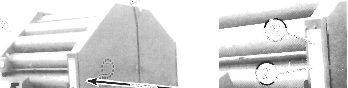
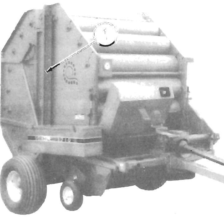
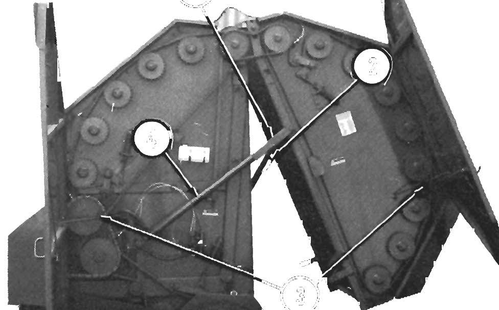
CROWDER WHEELS KIT (Fig. 15-3) The Crowder Wheels Kit (805423) is available for expanding the Pickup width of either model Baler to enable taking in a wider swath of material. The Kit contains (2) Crowder Wheels, Mounts and attaching hardware. Installation, operation and adjustments details are provided with the Kit of parts.
Fig. 15-3: Crowder Wheels (Installed)