2 minute read
CHA PTER 15

OPTIONAL FEATURES & AC CESSOR IE S
G Enera L Information
The following Optional Features & Accessories are available for installation on a Baler to increase is capabilities. Set-up and assembly information for all Kits , except the Twine Tie Mechanisms, are provided in sepa rate instructions packaged with each Kit of parts.
AUTO-ELECTR IC TIE SY STEM
The Auto-Electric Wrap System (805435) includes a tractor -m ounted Control Unit, remotely mounted Sensors, Power and interconnecting Cables, mounting Brackets and attaching hardware. Details for adaptation and op eration of the system are included in a appropriate section of this manual. The Auto-Electric Wrap System is designed to enable automatic and uniform wrapping of the bale with twine ..
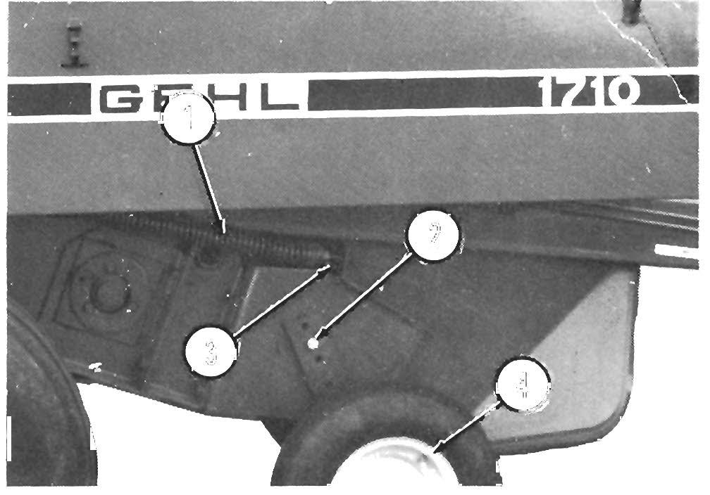
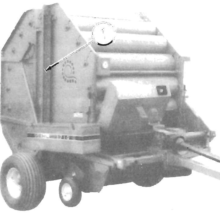
AUTOMATIC CHA iN O IL ER (F ig. 15-1)
The Automatic Chain Oiler (803642) provides a squirt of lubrication to all of the Drive Chains (except for the Pickup Drive Chain , as noted below) every time the Rear Door opens to discharge a bale . In this way, the Chains are oiled in direct proportion to the number of bal es produced. Installation details are included with the Chain Oiler Kit.


NOTE: The Pickup Drive Chain does NOT get oiled by the Au tomatic Chain Oiler an d MUST be manually oiled every 8 hours (or daily) Refer to the Drive Chains topic in the Lubrication chapter of this manual.
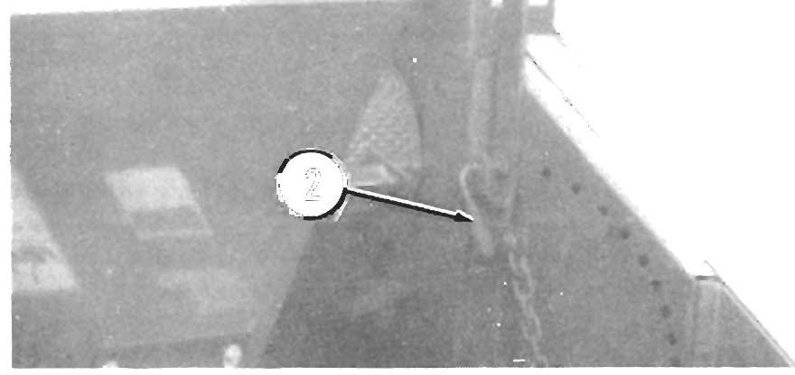
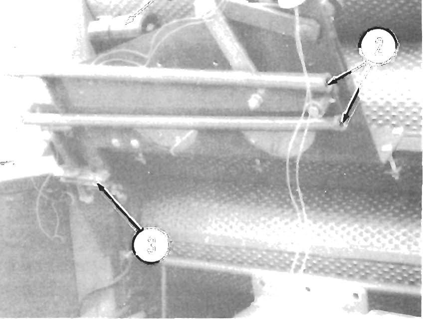
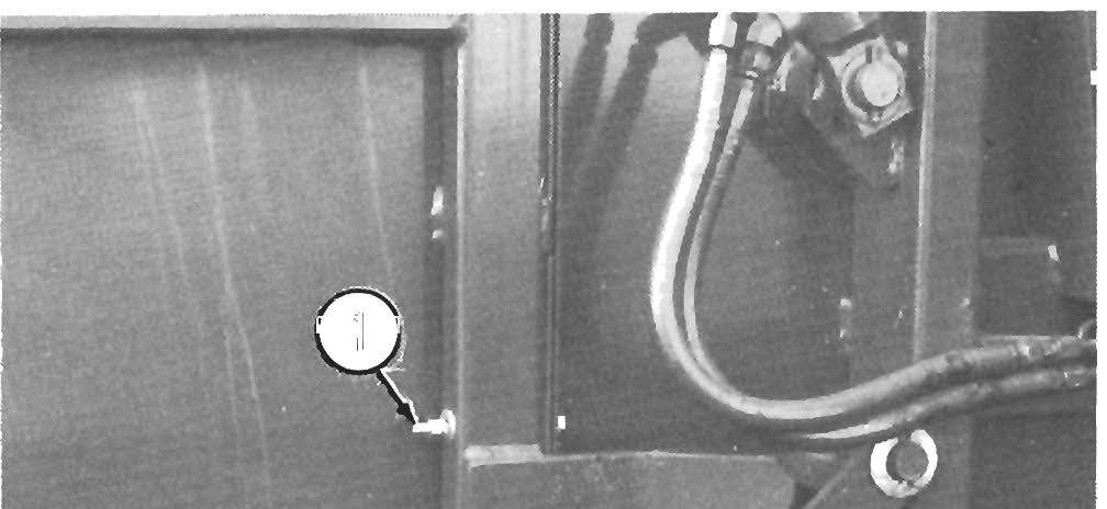
BALE DISCH ARGE BUM PER (Fig. 15-2)
The Bale Bumper (803643) is designed to roll the discharged bale back away from the Baler about 10 feet (3 meters) on level ground. This usually provides enough clearance to close the Rear Door without having to move the tractor forward. Installation instructions and mounting hardware are provided with the Bale Bumper.
1 • Bale Discharge Bumper (Installed)
Fig. 15·2

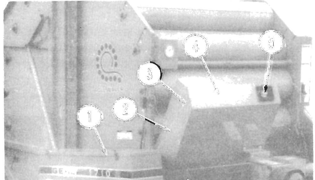
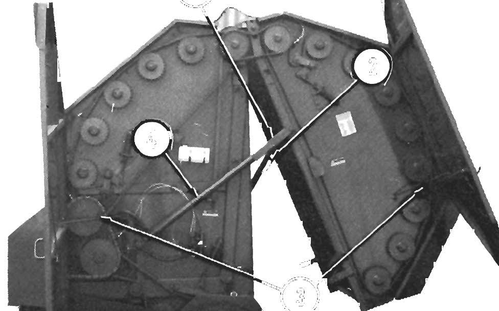
CROWDER WHEELS KIT ( Fi g. 15-3)
The Crowder Wheels Kit (805423) is available for expanding the Pickup width of either model Baler to enable taking in a wider swath of material. The Kit contains (2) Crowder Wheels, Mounts and attaching hardware. Installation, operation and adjustments details are provided with the Kit of parts.
NOTE: The optional Crowder Wheels Kit cannot be installed at the same time as the optional Gauge Wheel Kit because of interference with the right side mounting brackets.
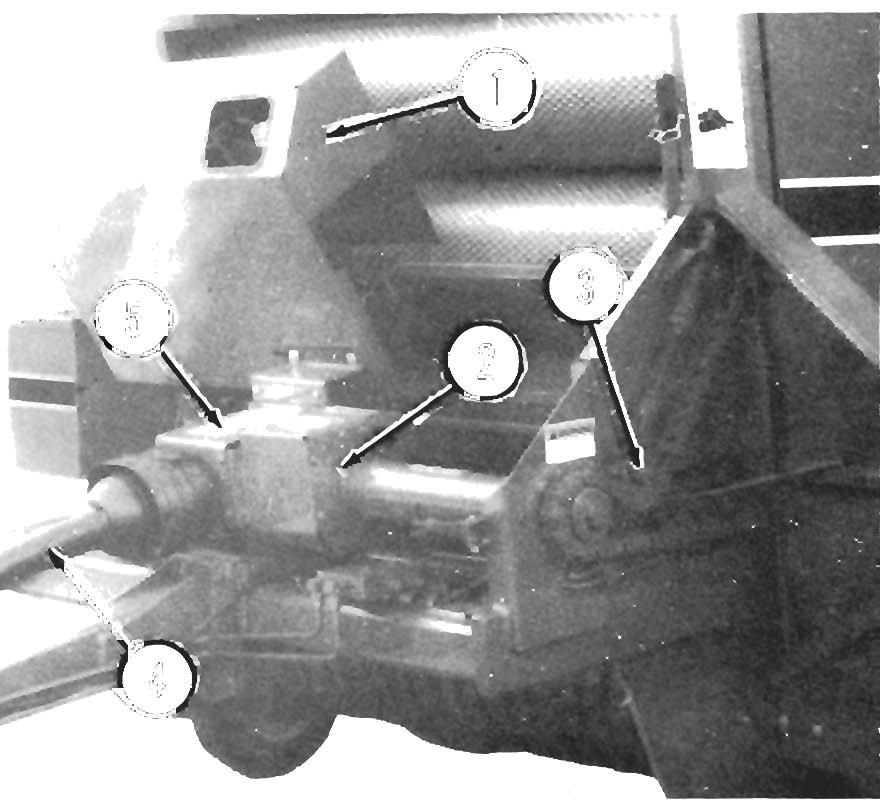
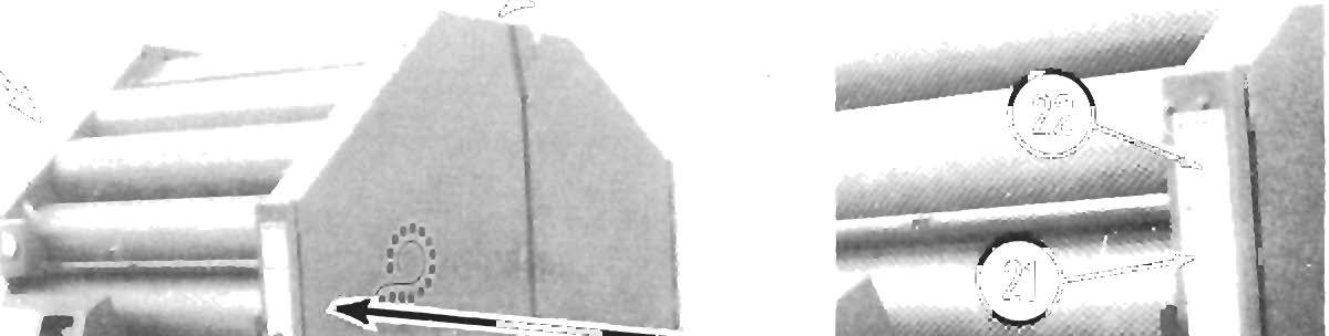
GAUGE WHEEL (Fig. 15-4)
The Gauge Wheel (803636) allows the Baler Pickup to better follow the contour of the ground and, thereby, reduces the possibility of the Pickup Tines contacting the ground. Installation instructions are provided with the Gauge Wheel.
NOTE: AFTER installing (or removing) the Gauge Wheel, BE SURE Pickup flotation is reset so that approximately 30 Ibs (14 kgs) of force is required to lift the Pickup at the Hay Hold-down Cross Pipe BEFORE operating the Baler or damage to the Pickup may result. Refer to the Pickup Flotation topic in the Adjustments chapter of this manual.
MANUAL-ELECTRIC TWINE TIE KIT
The Manual-Electric Twine Tie Kit (805028) is available for manual control of the Twine Tie mechanism. It contains a Control Box, Wiring and mounting hardware. Installation details are provided in the Setup & Assembly chapter.
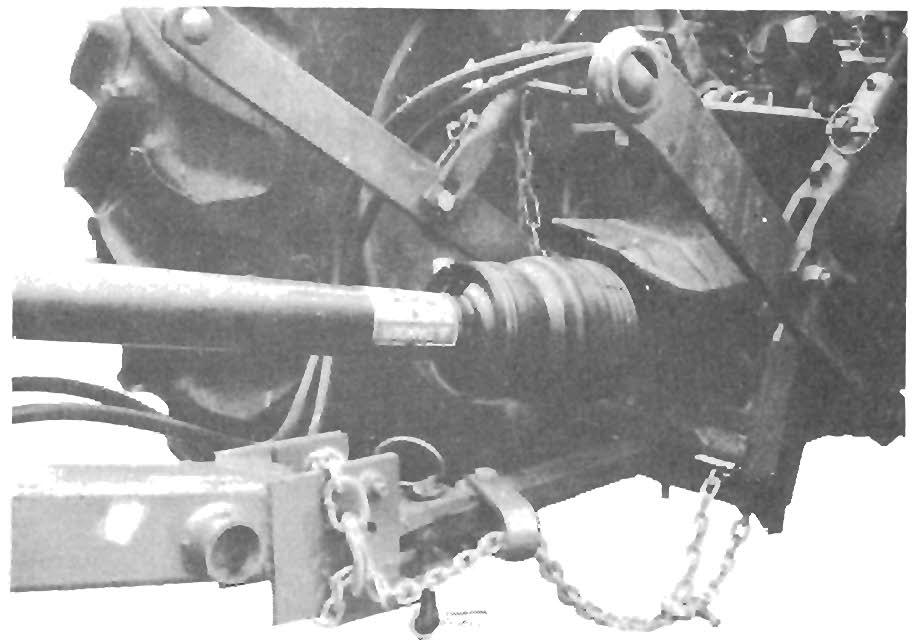
SAFETY CHAIN (Fig. 15-5)
NOTE: If the Baler is going to be transported on a public highway, Safety Chain Kit should be obtained and installed following the details in the "Controls & Safety Equipment" and "Transporting" Chapters.
The recommended Safety Chain for use with this Baler can be obtained in Kit 803320.