8 minute read
ADJUSTM ENTS


The Baler has been designed and factory adjusted to function properly under most field operating conditions. However, due to the wide range of operating conditions encountered, some additional readjustments may be required.
A Caution
BEFORE proceeding to perform any adjust· ments on this unit, exercise the MANDATORY SAFETY SHUTDOWN PROCEDURE (page 8).
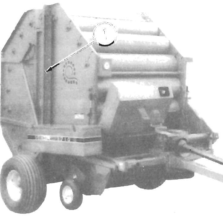
PICKUP HEIGHT (Fig. 7-1)
NOTE: The Baler Pickup should ALWAYS be run as high above the ground as possible while still being able to pick up all of the crop.
A Pickup Lever mechanism is provided on the left side of the Baler for raising and lowering the Pickup to make operating height adjustments.
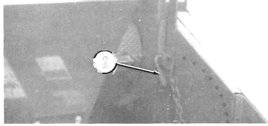
NOTE: A small Chain is provided on the left side of the Baler to lock the Pickup Lever when it is in the fully raised "transport" position. BE SURE the Chain is slipped over the end of the Pickup Lever whenever the Baler is being transported to ensure that the Pickup will remain in the raised position. 1 - Lock Chain
To raise or lower the Pickup , pull out on the Pickup Lever L a tch Rod and th e n mo ve the Pi ck up L e ver ov e r the hole in the Side Sheet , nearest to the desired pos ition. Release the Latch Rod while making sure the end of the Rod engages into the hole to lock the Pickup Lever at the desired setting. If the Baler is going t o be transported, move the Pickup Lever to the top position and secure it with the Lock Chain.
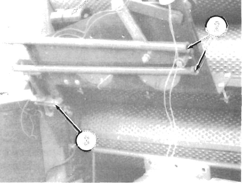
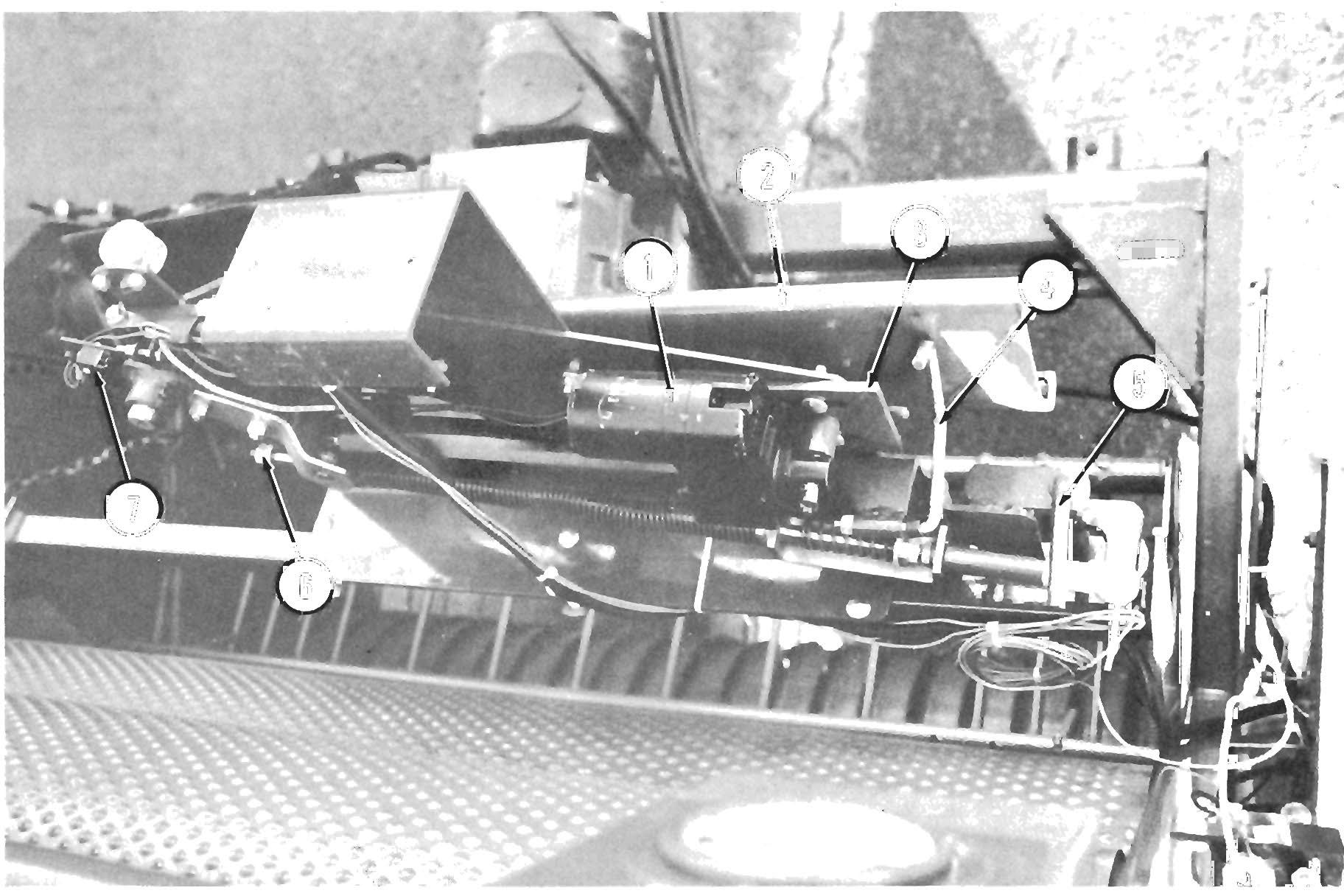
PIC K UP FL OT ATIO N (Figs. 7-2 & 7- 3)
NOTE: Proper flotation is determined with the Pickup in the "Iowered" position and with the Ora wba r Hitch Plate adjusted so that the Twinebox is p arallel w ith the ground.
The Baler is provided with a tensi o n a djustable, floating Pickup. For normal operating c onditions on relatively smooth ground , the recomm e nded Pickup Flotation Spring tension is approximately 30 pounds (14 kilograms) of lift required at th e cross pipe on the Hay Hold-down.
For extremely rocky or rough groun d co nditions, increase Pickup Flotation Spring ten si on to allow the Pickup to float easier. To increase Spring tension, proceed as follows:
NOTE: Measure the length of the Springs, BEFORE making any adjustments, so that the Pickup can later be restored to the initial setting . Also , make sure to adjust BOTH Springs equally.
On right side of Pickup, loosen the 1/2" Nut and turn the 1/2" Hex Tap Bolt clockwise to lengthen the Spring. After the proper adjustment is made, resecure the Tap Bolt with the 1/2" Nut.
On left side of Pickup, turn the Lock Nut, located on the Spring mounting 3/8" Eye Bolt, counter-clockwise (as viewed from the bottom of the Baler) to lengthen the Spring.

NOTE: The Lock Nut and 318" Eye Bolt, on the left side of the Pickup, have left hand threads.
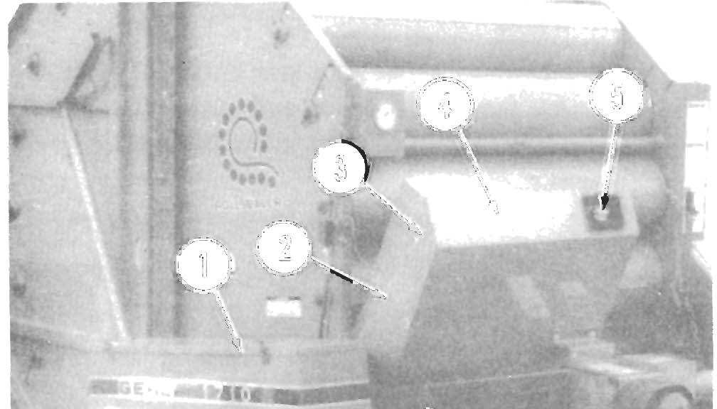
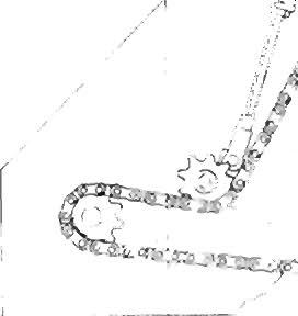
1 - 1/4" (6 mm) Deflection
2· Pickup Flotation Spring (Left Side)

3· Pickup Drive Chain Idler Sprocket
4 • 3/S" Eye Bolt & Lock Nut
Fig. 7-3

Drive Chain Tension
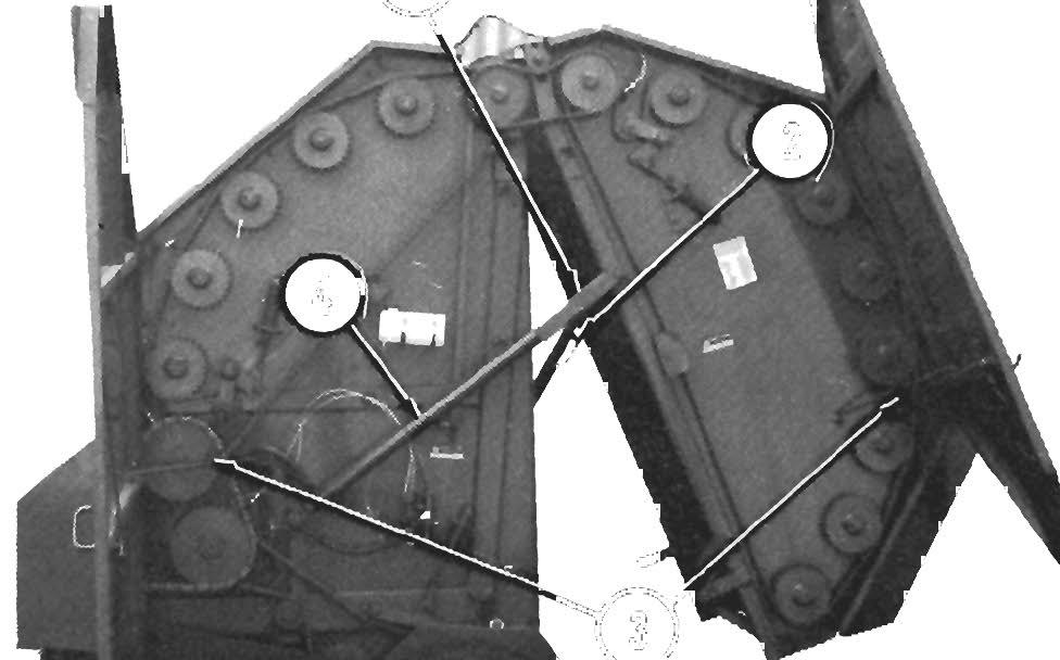
Main, Front Lower, Front Upper & Rear Door Rollers Drive Chains (Fig. 7-4)
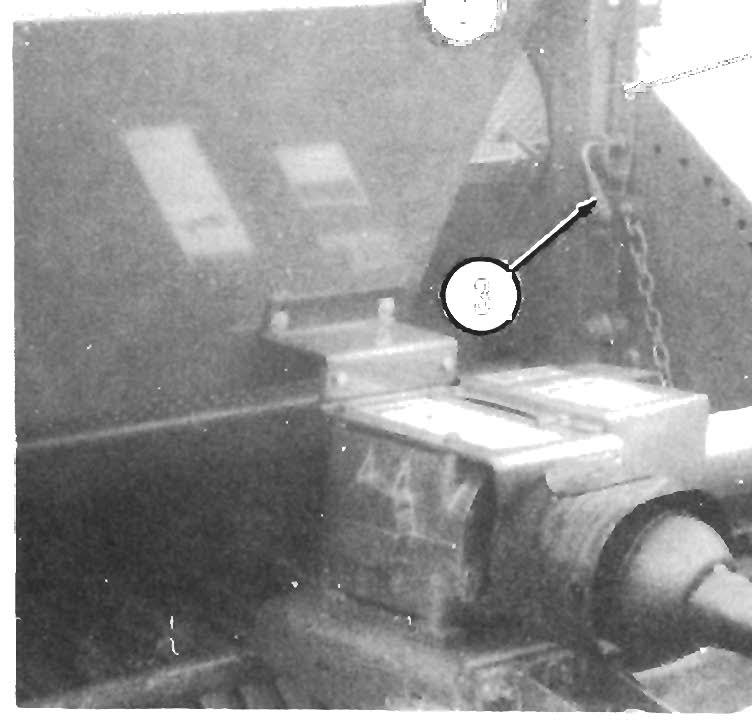
The Baler Main Drive, Front Lower Drive, Front Upper Drive and Rear Door Rollers Drive Chains are provided with adjustable, spring-loaded Chain Tensioners and Idler Sprockets. Proper Chain tension is obtained when the distance between the Chain Tensioner Mounting Bracket and the Spring Guide or Jam Nut Washer is 1-3/8" (35 mm) as shown.
To adjust, loosen the Jam Nut and then, using a wrench, turn the Spring Guide in or out, until the proper distance is obtained. BE SURE to retighten the Jam Nut against the Spring Guide, after making the adjustment.
NOTE: Check for proper Chain tension on a daily basis. DO NOT operate the Baler with less than 112" (13 mm) of clearance between the Chain Tensioner Mounting Bracket and the Spring Guide or Jam Nut Washer or Chain failure will result.
A - Front Upper Rollers Drive Chain Tensloner
B
• Rear Door Rollers Drive Chain Tensioner
C· Main Drive Chain Tensloner
D
• Front Lower Rollers Drive Chain Tensioner
1 • 1-3/S" (35 mm)
Fig. 7-4: Drive Chain Tensioners
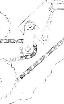
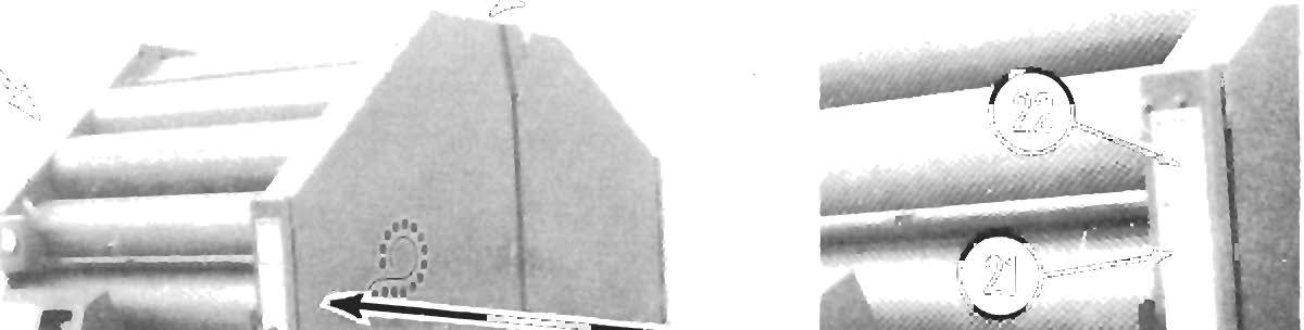
Pickup Drive & Rear Door Connector Drive Chains (Fig. 7-5 & See Fig. 7-3)

The Baler Pickup Drive and Rear Door Connector Drive Chains are provided with adjustable Idler Sprockets for setting proper Chain tensions. Proper Chain tension is determined when 1/4" (6 mm) of deflection is present on the strand of Chain opposite the Idler Sprocket.
Chain tension can be adjusted by loosening the Idler Sprocket mounting hardware and then sliding the Sprocket up or down in the guide until the proper setting is obtained. BE SURE to retighten the Idler Sprocket mounting hardware after adjusting the Chain tension.
GAUGE WHEEL HEIGHT (See Fig.7-2)

NOTE: The accessory Gauge Wheel height should be adjusted so that the Pickup Tines are a minimum of 1" (25 mm) from the ground. Normal ground clearance, for most crop conditions, requires that the Gauge Wheel be adjusted so that the Pickup Tines are 1-112" to 2-112" (38 to 64 mm) above the ground.
To adjust the accessory Gauge Wheel height, remove the (2) 1/2 x 1-3/4" Cap Screws, Lock and Plain Washers securing the Spindle Assembly to the Pickup Right Side Assembly. Three sets of holes are provided in the Spindle Assembly to obtain proper Pickup Tine ground clearance.
Twine Tie System
Twine Placement (Figs. 7-6 & 7-7)
To adjust twine placement on the right hand side of the Baler:
1. Loosen the hardware attaching the Twine Mounting Plate to the Crosstube assembly.
2. Slide the assembly right or left to obtain the desired position.
NOTE: The twine placement on the right hand side can be predetermined by measuring the distance between the right inside edge of the bale chamber and the center of the Clamp Jaw Pivot Rod.
3. Retighten the Twine Mounting Plate attaching , hardware.
To adjust twine placement on the left hand side of the Baler:
1. Completely extend the Actuator.
2. Loosen the hardware on the Actuator Adjustment Bracket.
3. Place the Twine Arm to the desired position and retighten the Adjustment Bracket hardware.
Clamp Jaws (Figs. 7-6 & 7-7)
Latch Position
To properly adjust the Clamp Jaw Latch position, fully extend the Actuator. Then, adjust the Spring Slide Rod so that the Clamp Jaw Pivot Rod rotates below the Catch on the Trip assembly. When this position is obtained, tighten the Jam Nuts.
Latch Tension
To adjust the Clamp Jaw Latch tension, rotate the Locknut on the Clamp Jaw Pivot Rod. The tighter the Spring is compressed, the greater the tension on the twine.
NOTE: The following information applies only to a Baler which is equipped with an Auto-Electric TwIne TIe system.
Delay Switch Position (See Fig. 7-7)
Stroke the Actuator to move the Twine Arm to within 6 to 8" of the Cutoff Trip Arm. Then, with the Delay Switch Clamping hardware loose, rotate the Switch assembly clockwise until the Roller causes the Switch contacts to just transfer (click). Then, tighten the Clamping hardware.
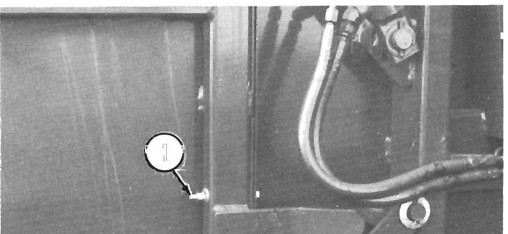
Twine Tube "Pause" Placement (Fig. 7-8)
NOTE: If Control Box does NOT have an external Adjustment Knob (as shown), dealer MUST be contacted to perform the following adjustment.
1
2

3
With tractor engine running, push the "Recycle" But ton and observe where or at what position the Twine Arm pauses. If the pause is before the Clamp Jaws are at least halfway open, turn the Adjustment Knob clockwise about 10'. Test this adjustment by recycling the system. Continue to readjust, as necessary.
Twine Tension
This unit is provided with a Twine Tensioner Assembly for increasing or decreasing Twine Tension. After the first few bales have been tied and the twine cut, it may be necessary to adjust the Twine Tensioner so that 18" (457 mm) of twine extends from each of the Twine Delivery Tubes. A Wing Nut and Spring mechanism on the Twine Tensioner is provided to increase or decrease the amount of tension on the twine. Turning the Wing Nut clockwise, which increases twine tension, will result in shortening the amount of twine extending from the Tubes; turning the Wing Nut counterclockwise, which decreases twine tension, will result in lengthening the am<?unt of twine.
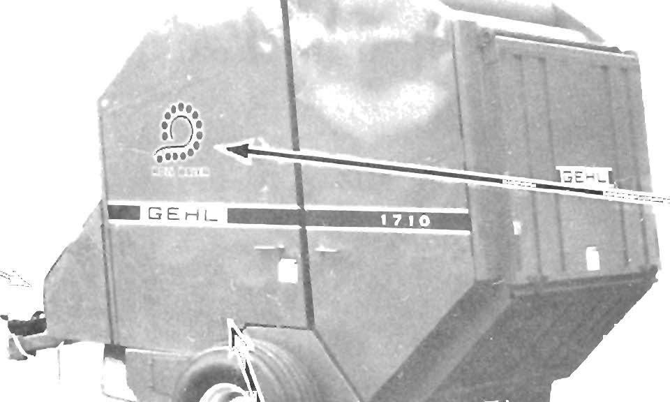
Wheel Axle Positioning
The 1710 Baler is provided with dual-position Wheel Axles for making track width adjustments. Refer to the Dual-position Wheel Axle topic in the Preparing for Field Operation chapter for adjustment details.
General Infor Mation
Acaution
NEVER attempt to lubricate the Baler when any part of It Is In motion. ALWAYS, BE SURE to exercise the MANDATORY SAFETY SHUT· DOWN PROCEDURE (page 8) BEFORE proceeding to lubricate the Baler.
Gearbox
NOTE: On a routine basis after every 100 hours of operation, check the fluid level in the Baler Gearbox. The level should be maintained, with a sufficient amount of SAE 90 Gear Lube, so that it just starts to run out of the Inspection Plug opening at the back of the Gearbox. Add fluid, as necessary, through the Gearbox Inspection Plug opening.
The Gearbox should be checked occasionally for oil drips and dust accumulation around the Seals which would indicate that the Seals are leaking. Oil which is tan in color and foams excessively indicates that it has water present in it. However, unless rust spots are visible inside the Gearbox, the fluid does NOT require replacement.
NOTE: ON an annual basis, drain, flush out and refill the Gearbox with new SAE 90 Gear Lube. Do NOT overfill the Gearbox; only fill to the bottom of the Inspection Plug opening.
ROLLER CHAINS & PTO DRIVE SHIELDS
Lubricate all Roller Chains every 6 to 8 hours of operation using a good grade of foaming aerosol lubricant, such as NAPA Chain and Cable Lubricant. This type of lubricant increases the life of the Chain 3 to 4 times over those lubricated at 8 hour intervals with new or used motor oil. The recommended method is to spray the entire length of Chain on the center of the Rollers. It is better to lubricate Chains when they are warm (after use, rather than before)
NOTE: For Balers equipped with the accessory Automatic Chain Oiler, fill Oil Reservoir Tank as often as required with a lightweight oil (SAE 10 or equivalent) Usually, a full Tank should provide adequate lubrication for producing 100 or more bales.
In addition to the Roller Chains, apply oil or foaming aerosol lubricant to the Telescoping PTO Drive Shields.
NOTE: At the end of the harvesting season, coat all of the Roller Chains (and any other unpainted, exposed metal) with oil before placing the Baler into storage.
Sealed Bearings
Sealed Bearings are lubricated for life and relubrication is NOT required, NOR should it be attempted.
GREASING General
NOTE: Use an SAE mUlti-purpose, Lithium base grease for all locations.
Clean, inspect and repack the Wheel Bearings at least once a year.
Grease Fittings
NOTE: Grease all Fittings at the intervals of operation listed. Also grease all Fittings before and after storing the Baler and as otherwise listed.
Wipe dirt from the Fitting, before greasing it, to prevent any dirt from being forced into the Bearings or pivots Replace any missing or defective fittings, when noted. To minimize dirt build-up, avoid excessive greasing.
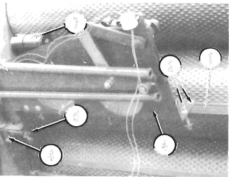
Grease Fitting Locations
Grease Every 8 hours (or Daily)
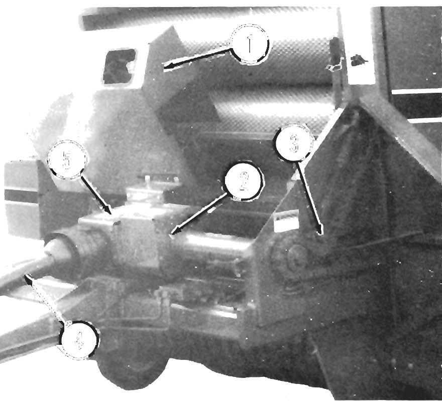
Telescoping PTO Drive Crosses (4 Places)
2 Pickup Tine Bar Spider Assemblies (8 Places -4 Each Side)
3 Pickup Pivot (1 each side)
Grease Every 40 hours (or Weekly)
4 Telescoping PTO Drive Shield (2 Places)
Grease Every 100 hours (or Annually)
5 Rear Door Pivot (1 each side)
6 Twine Tie Pivots (2 Places)
7 Idler Pivot Brackets (4 Places)