9 minute read
GENER AL INFO RMATION A C A UT I ON

BEFORE starting to do ANY Service routines on this unit, exercise the MANDATORY SAFETY SHUTDOWN PROCEDURE (page 8).
NOTE: The following information is also referredto in the Troubleshooting chapterofthis manual. It should be understood that all services, detailed in this chapter, are Owner-Operator responsibilities. Where indicated, certain service routines should only be carried-out by (or under the direction of) an authorized GEHL Dealer or GEHL Company representative.
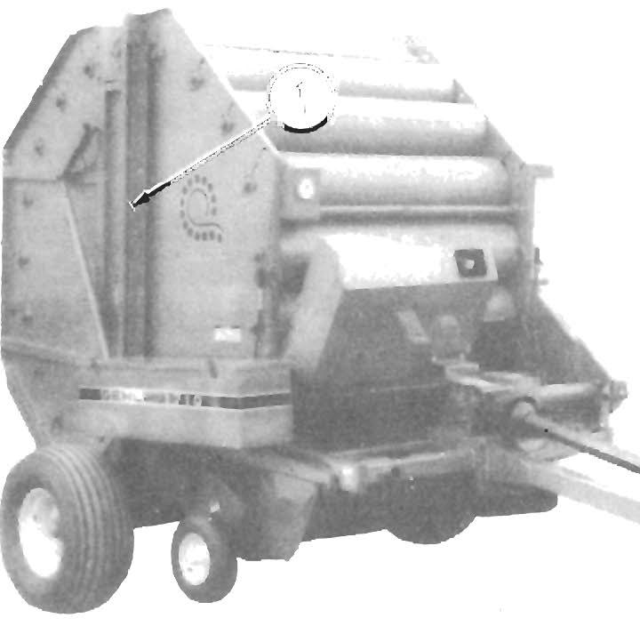
Sealed Ball Beari ng Replacement (Fig. 9-1)
Sealed Ball Bearings are used on ·various Shafts on the Baler. This type of Bearing is generally retained with a Self-locking Eccentric Collar. The Lock Collar has a counterbored recess, which is eccentric with the Collar bore. This eccentric recess engages or mates with an eccentric end of the Bearing inner ring, when the Bearing is assembled on the Shaft. The Bearing is engaged, on the inner ring cam, by the Collar. This assembly grips the Shaft tightly with a positive binding action that increases with use. The Collar Set Screw provides supplementary locking.
The Bearing can be removed from the Shaft by loosening the Set Screw and then tapping on a punch, which is placed in the drift pin hole, to loosen the Collar. Install Bearings with self-locking Collars in the following manner:
1. Place the Bearing and Collar on the Shaft with the cam surfaces next to each other. Tighten the bolts on the Bearing Retainers.
2. Mate the cam, of the Lock Collar, with the cam, of the Bearing inner ring.
3 Press the Lock Collar against the Bearing's wide inner ring cam and turn it, in the direction of Shaft rotation, until it tightly engages. Tighten the Collar further, by tapping on a punch inserted in the drift pin hole.
NOTE: To avoid damaging the Lock Collar, do NOT overtighten it.
4. Tighten the Set Screw in the Lock Collar.
Gib Key
The Gib Key, a tapered key with a tang on the thick end, is a combination locking device and hub retainer. The Gib Key will lock the hub in place and retain it from turning. The hub MUST have a matching tapered keyway for use with the Gib Key.
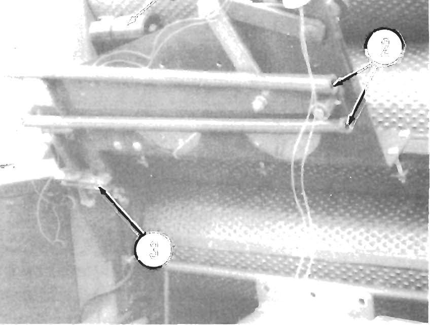
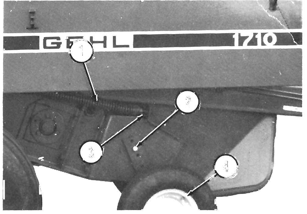
Removal (Fig. 9-2)
1. Remove paint from the Shaft on both sides of the hub.
2. Loosen the Set Screws.
3. Drive hub away from Key head, using a large punch or drift. Make sure that Gib Key does NOT move with hub.
4. Pull Key, using a pinch bar or tapered punch.
5. Slide hub from Shaft.
Installation (Figs. 9·3 & 9·4)
6. Align Sheave or Sprocket and place Key in keyway.
7. Reseat Key with a lead-headed hammer (or rubber mallet), without moving Hub on Shaft.
Fig. 9·1
NOTE: The Key does NOT have to be driven extremely hard, in order to hold.
Fig. 9-2
When installing a new Gib Key into the Sprocket hub, it may be necessary to file the Gib Key to obtain a good Key length engagement. When doing this, BE SURE to file the bottom side of the Key, NOT the tapered top side.
When filing, use a hand file and use a smooth even motion to take enough material off. Do NOT use any type of power grinder on the Gib Key or a poor fit can result.
A Gib Key has a taper of 0.0104 in/in. To check taper, when filing, put two marks on the Key, 1 inch apart, and use a caliper to measure the taper.
1 - File evenly on this side
2 - Sprocket
3 - 1/16" minimum gap on all keys
4 - Gib Key
5 - Shaft
6 - Sprocket Hub
7 - 1/2" maximum or flush with end of Shaft
Fig. 9-4: Proper Glb Key Installation Detail
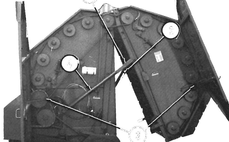
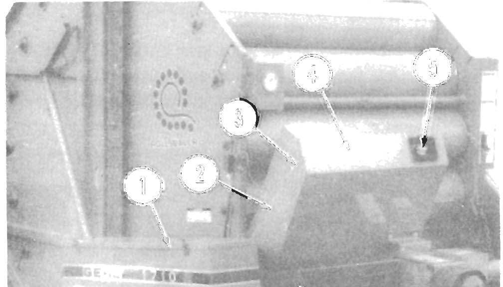
DRIVE CHAINS (Fig. 9-5)
The RB1710 Baler has a total of six roller-type Drive Chains including:
- Main Drive Chain, #100HK of 78 Links with (1) Spring Clip-type Connecting Link (Slip-fit).
- Front Upper Drive Chain, #80 of 184 Links with (1) Spring Clip-type Connecting Link and (1) Offset Link.
- Rear Door Connector Drive Chain, #60H of 69 Links with (1) Spring Clip-type Connecting Link (Slip-fit) and (1) Offset Link.
- Rear Door Rollers Drive Chain, #60 of 290 Links with (1) Spring Clip-type Connecting Link (Slip-fit) and (1) Offset Link.
- Front Lower Drive Chain, #80 of 127 Links with (1) Spring Clip-type Connecting Link and (1) Offset Link.
- Pickup Drive Chain, #60 of 79 Links with (1) Spring Clip-type Connecting Link (Slip-fit) and (1) Offset Link.
7-1/2" to 7-3/4" (maximum), for a #80 Chain, it should be 10" to 10-5/16" (maximum) and for a #100HK Chain, it should be 12-1/2" to 12-7/8" (maximum). If the distance measured is greater than the "maximum", replace the Chain.
NOTE: Replace the Drive Chain when the Chain Tensioner for that particular Chain only has 112" (13 mm) of adjustment remaining. Do NOT shorten the Chain by removing a Link (or Links).
Chain Removal & Installation
All six Drive Chains on the Baler are provided with Spring Clip-type Connecting Links to aid in Chain removal and installation.
NOTE: BEFORE attempting to remove the Spring Clip-type Connecting Link from a Drive Chain, to remove the Chain for service, release the tension on the Chain by loosening its Chain Tensioner. Also, BE SURE to adjust the Chain for proper tension, after installing a cleaned and re-oiled (or a new) Chain. Refer to the Adjustments chapter in this manual, for details.
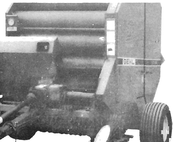
GEARBOX (Fig. 9-6)

1 • Front Upper Drive Chain
2· Rear Door Connector Drive Chain
3· Rear Door Rollers Drive Chain
4
• Front Lower Drive Chain
5
• Pickup Drive Chain
6
• Pickup Clutch & Sprocket
7· Main Drive Chain
Fig. 9-5
Sprocket wear is most often caused by an excessively worn Drive Chain. Factors such as operating conditions (dirt and temperature), amount of power transmitted, operating speed of the chain and lubrication (or lack of it) influence the life of the Chain.
To effectively lubricate the Chain joints, lubricant should be delivered to the spaces between the side bars. It is also essential, that an adequate lubricant film be retained between the rollers, bushings and pins to maintain a flexible Chain. If a Chain becomes stiff, remove it and soak it in a solvent to loosen dirt and corrosion from the joints. Then, wash the Chain in clean solvent and soak it overnight in oil so the oil can penetrate between all joints.
A Chain which has worn 3% (1.03 times its original length), should be removed and replaced. To determine the amount of wear on a particular Chain, an easy check is to measure 10 Links of the Chain in a straight line, from the center of one pin to the center of the 10th following pin. For a #60 Chain, the distance should be
The Gearbox can be removed from the Baler for taking it to a GEHL Dealer for internal component service.
NOTE: Internal Gearbox component repairs and/or replacements should only be attempted by (or under the direction of) an authorized GEHL equipment dealer.
Removing Gearbox
To remove the Gearbox from the Baler, proceed as follows:
1. Release the Chain tension and then uncouple the Main Drive Chain. Refer to the Drive Chains topic in the Adjustments chapter and in this chapter, for detailed instructions on Drive Chain removal.
2. Remove the PTO from the Gearbox Shield.
3. Loosen the 4" Clamp on the Jackshaft Shield.
4. Remove the hardware securing the Twine Tie Guard to the Gearbox Shield. Then, remove (4) 5/16-18 x 3/4" Flanged Head Locking Cap Screws and the Gearbox Shield.
5. Remove the (3) 5/8 x 2-1/2" Cap Screws and Lock Nuts securing the Splined Coupler (Gearbox side of the Rubber Coupler Assembly) to the Rubber Coupler Ring.
NOTE: Do NOT lose any of the Shims when removing the Gearbox mounting Bolts in step 6. The Shims are used to obtain proper alignment between the Gearbox Output Shaft and Jackshaft. Refer to the Jackshaft Alignment topic later in this chapter for more details.
6. Remove the (4) Grade 8 Cap Screws and Lock Washers located at the bottom of the Gearbox and then remove the Gearbox, all Shims and the (4) 3/8" thick Spacer Bars. Remove the Splined Coupler from the Gearbox Output Shaft (Coupler has a sliding fit on Shaft).
Installing Gearbox
7. To install the Gearbox, reverse the steps for "Removing Gearbox" and take into account the following noted information.
NOTE: Refer to the "Main Drive Jackshaft & Rubber Coupler" topic, next in this chapter, to obtain proper alignment between the Gearbox Output Shaft and the Main Drive Jackshaft. Also, BE SURE to properly adjust the Main Drive Chain tension following the details in the Adjustments chapter.
8. Fill Gearbox to the proper level with SAE 90 Gear Lube. Refer to the Lubrication chapter for additional details.
MAIN DRIVE JACKSHAFT & RUBBER COUPLER
Power, from the Baler Gearbox, is transmitted to the Main Drive Chain and Sprockets through the Rubber Coupler and Main Drive Jackshaft. The Rubber
Coupler not only provides a means of connecting the Gearbox Output Shaft to the Jack shaft, but it also provides cushioning from high shock loads due to engaging and disengaging the PTO.
NOTE: The Jackshaft and Gearbox Output Shaft MUST be maintained in proper alignment at ALL times. Anytime the Jackshaft or Gearbox has been removed, proper alignment MUST be re-established during reassembly.
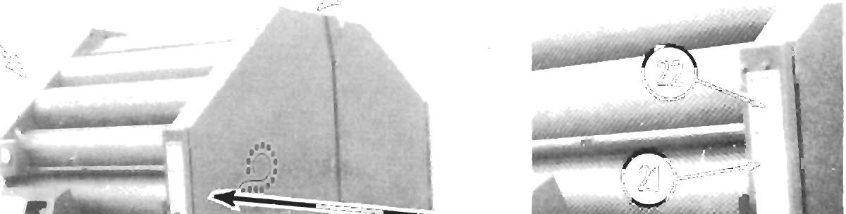
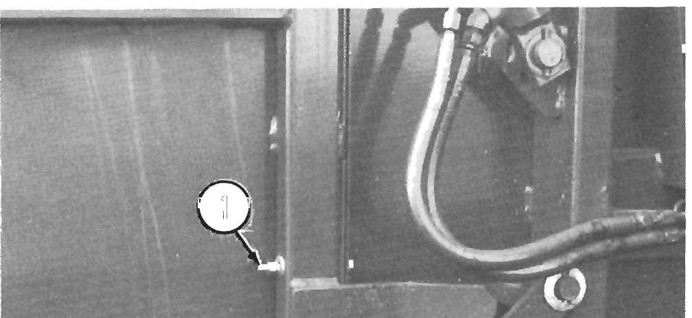
Jackshaft Alignment (Fig. 9-7)
When installing the J ackshaft, maintain a distance of 4-1/8" (lOS mm) between the end of the Jackshaft and the Bearing Support Plate as shown in the illustration. Check for parallel alignment (within 1/32" vertically and horizontally) between the Jackshaft and the Gearbox Output Shaft (it may be necessary to Shim and/or to twist the Gearbox, in order to obtain parallel alignment). Once aligned and BEFORE tightening the (6) Coupler bolts, measure the total runout of the Jackshaft.
NOTE: When measuring for total runout, the Main Drive Chain MUST be disconnected and the Gearbox Input Shaft MUST be rotated by hand in order to obtain accurate results. 1
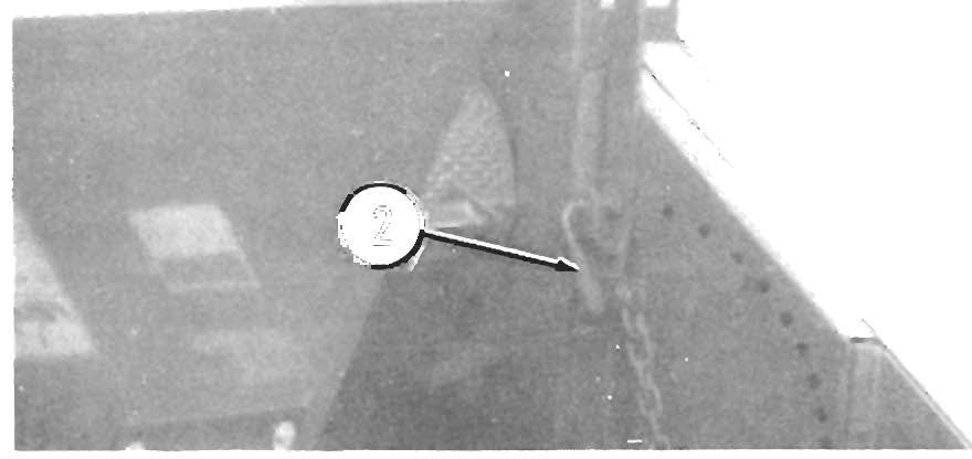
REAR
The Rear Door should be inspected on a routine basis every 100 hours of operation.
Check the:
- Rear Door Pivots for adequate lubrication and ease of op e ration . The Door should open and close smoo thly with out any binding.
- Cylinders and Cylinder Locks for proper operation. The Cylinders should extend and retract smoothly, without any binding and the Cylinder Locks should engage and disengage, without any restrictions or binding .
Awarning
Do NOT test for hydraulic fluid leaks with your bare hands; use a piece of cardboard or wood fortesting. Escaping fluid under pressure can be Invisible and can penetrate the skin which will cause a serious Injuryl If escaping fluid Is Injected Into your skin, see a doctor at once. Injected fluid MUST be surgically removed by a doctor familiar with this type of Injury or gangrene may result. Remove all pressure from the Hoses, using the tractor hydraulic controls, BEFORE attempting to service the Baler Rear Door hydraulic system.
- Rear Door Cylinders, Control (Relief) Valve and Hydraulic Hoses and Fittings for external leaks. Tighten or replace Hoses and Fittings, as necessary.
NOTE: If the Baler hydrauliC system does NOT hold a Gauge pressure of 1000 to 2000 PSIG for 20 seconds, or more, with cool oil, an internal malfunction is likely and the Baler should be taken into your Gehl dealer for testing and repair.
Ac A U Tion
Hydraulic System testing and repair should only be attempted by (or under the direction of) an authorized GEHL equipment dealer.
1 • Rear Door Pivot (1 each side)
2· Cylinder Lock In "Engaged" Position (1 each side)
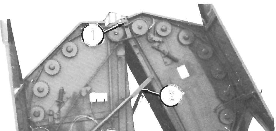
Fig 9-10
Pto Drive Line
NOTE: Repair of the PTO Drive Shafts, Joints and/or the Center Bearing should only be attempted by (or under the direction of an authorized GEHL equipment dealer.
Check that the PTO Shields rotate freely on the PTO Shafts. Properly lubricate per details in Lubrication chapter.
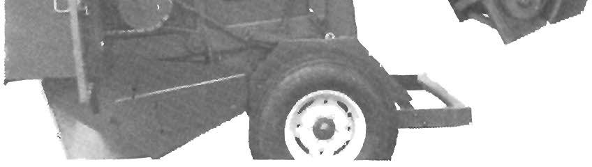
TIRES & WH EELS
The Tires should be inflated to the appropriate pressure listed in the Tire Pressures table. The Baler Wheel Lug Nuts should be torqued to 90 ft-Ib.
Awarning
Acaution
GEHL Company does NOT sell replacement Tires. In addition, Tire mounting, repair and replacements should ONLY be attempted by a qualified tire manufacturer's representative or by properly trained personnel following the tire manufacturer's instruction. If you do NOT have such Instructions, contact your tire dealer or the GEHL Company.
Inflating or servicing tires can be dangerous. Whenever possible, trained personnel should be called to service and/or mount tires. In addition, do NOT place fingers on tire bead during Inflation; serious injury or amputation could result! In any event, to avoid possible fatal or serious Injury, follow the safety precautions below:
• BE SURE the Rim Is clean and free of rust. Lubricate both the tire beads and rim flanges with a soap solution. Do NOT use 011 or grease.
• Use a Clip-on tire chuck with a remote hose and gauge which allows you to stand clear of the tire while inflating It.
Tire Pressures
• NEVER Inflate beyond 35 PSI (240 kPa) to seat the beads. If beads have NOT seated by the time the pressure reaches 35 PSI, deflate the assembly, reposition the tire on the rim, re-Iubricate both and reInflate It. Inflation pressure bey\ond 35 PSI with unseated beads may break the bead or rim with explosive force sufficient to cause fatal or serious injury.
• After seating the beads, adjust the Inflation pressure to the recommended operatIng pressure listed.
• Do NOT weld, braze, or otherwise attempt to repair and use a damaged rim.