15 minute read
A WAR N I NG

BE SURE that the PTO Shafts and Connec· tlons are free to rotate Inside the Shields BEFORE starting the tractor engine!
Gearbox & Jackshaft Shields
(See Fig. 5·1)
The Gearbox and lackshaft Shields are bolted in position and MUST remain securely fastened, except for servicing.
Main Drive Shield (See Fig. 5·1)
This hinged Shield, which is held closed by a Latch, covers and protects the front section of the Main Drive Chain mechanism. A Holder Rod is provided with the Shield to hold it open while servicing or making adjustments inside. BE SURE to keep the Shield closed and latched whenever the Baler is in operation.
Holder Rods are provided on the Doors to hold them open while servicing or making adjustments inside. BE SURE to keep the Side Doors closed and latched whenever the Baler is in operation.
Also located on the left side of the Baler are a hinged and Latched Shield (near the bottom front) to cover and protect the Pickup Drive and two bolt-on Shields (along the bottom) which are for service access during maintenance.
Rear Door Dust Panels (See Fig. 5-2)
The Baler Rear Door is provided with Dust Panels, which also serve as Shields to protect the Rear Door Rollers. The hinged Upper Dust Panel is secured with two (2) Rubber hook-type Latches to provide for easier access to remove accumulated dust. The Lower Dust Panel is secured with six (6 each) Cap Screws, Nuts and Washers.

Ac Auti O N
BEFORE proceeding to perform any work on the Baler and, BEFORE removing or opening any Shields, BE SURE to exercise the MAN· DATORY SAFETY SHUTDOWN PROCEDURE (page 8). Also, BE SURE to reinstall and/or close ALL Shields BEFORE operating the Baler.
Left Side Shields & Doors
Two large, hinged Side Doors, with Latch Handles, are provided on the left side of the Baler to cover and protect the Rollers and Rear Door Drive mechanisms.
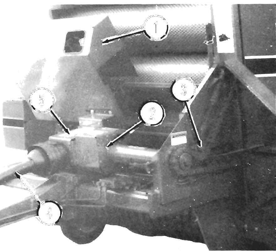
1 - Cylinder Lock In "Engaged" Position (1 each side)
2 - Cylinder Lock Latch Rod (1 each side)
3 • Side Door Holder Rods
4 - Rear Door Cylinder (1 each side)
Fig. 5-3
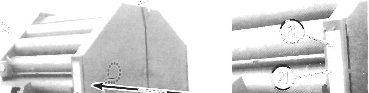
Rear Door Cyli Nd Er Locks
(Fig. 5-4 & See Fig. 5-3)
Awarn I Ng
ALWAYS engage the Rear Door Cylinder Locks BEFORE working Inside the Bale Cham· ber or anywhere under th e Rear Door when the Door Is open. ALWAYS engage BOTH Locks to make sure the Door Is properly supported. BE SURE that BOTH Cylinder Locks are fully engaged.
During normal operation, each Cylinder Lock is secured in its "storage" position by a Latch Rod and Spring mechanism. To engage the Cylinder Lock, the Latch Rod MUST be pulled down, to release the Cylinder Lock, BEFORE ra i sing the Rear Door. After the Door is opened completely, check both Locks to see if they are positioned properly and then lower the Door until it is resting on the Cylinder Locks.

A Wa Rnin G
BE SURE the Lock Pin Is properly inserted through both "Jack Supporting Position" Hub holes BEFORE disconnecting the Baler from the tractor.
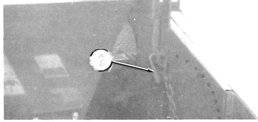
1 - Cylinder Lock In "Storage" Position (1 each side)
Fig. 5-4: Cylinder Lock In "Storage" Position


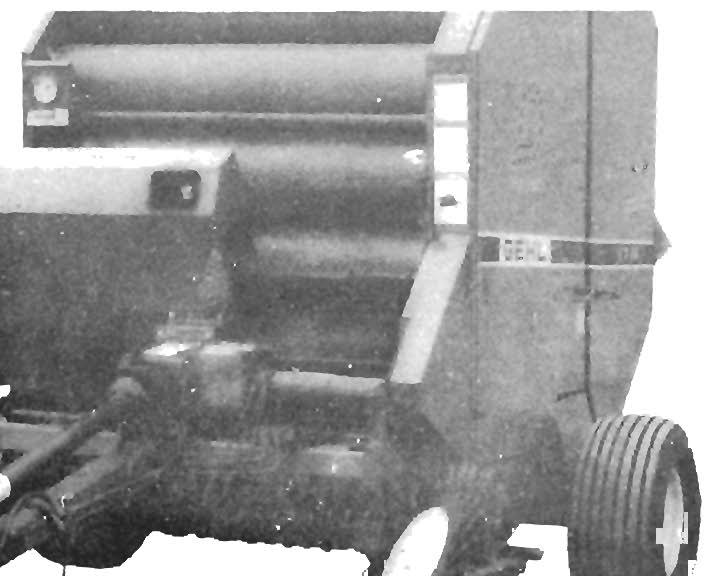
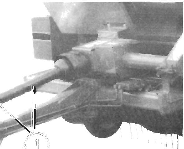
HITCHJACK (Fig s. 5-5 & 5-6)
A Hitchjack is furnished with the Baler to support the machine when the tractor is disconnected as well as to facilitate aligning the Hitch Clevis Plate with the tractor drawbar for hookup.

When the Jack is NOT being used to support the Baler, it can be removed and relocated to a "Jack Storage Position" Hub, located on the right front of the Baler Main Frame.
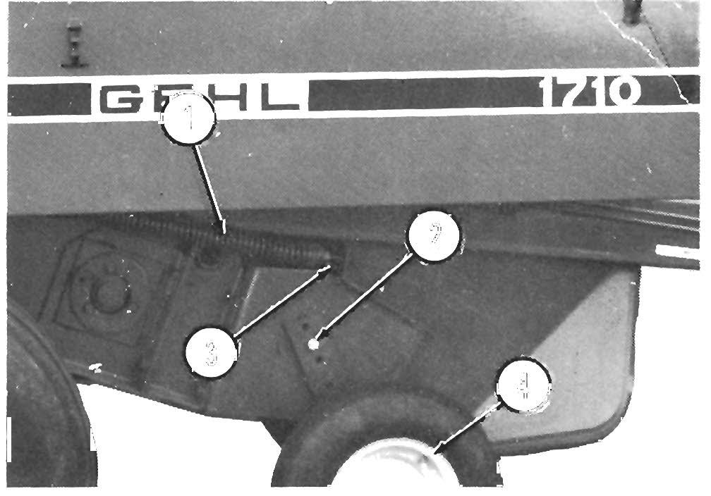
1 - Lock Chain
2· Pickup Height Adjustment Lever in "Transport"
Position
3 - Pickup Lever Latch Rod
4 - Lock Pin & Chain
5 - HltchJack In "Supporting" Position
6 - HitchJack Storage Hub
Fig. 5-5
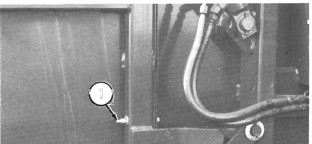
1 - Pickup Height Adjustment Lever In "Operating"
Position
2 - Pickup Lever Latch Rod
3 - Lock Pin & Chain
4 - HltchJack "Stored"
5 - Pressure Switch (Used w/Auto-electrlc Tie, Only)
6 - Pressure Gauge
Fig. 5-6
PIC KUP LEV ER /(See Figs . 5-5 & 5-6)
A Pickup Lever mechanism is provided on the left side of the Baler for raising and lowering the Pickup to make operating height adjustments.
NOTE: A small Lock Chain is provided on the left side of the Baler to lock the Pickup Lever when it is in the fully raised "transporting" position. BE SURE the Chain is slipped over the end of the Pickup Lever whenever the Baler is being transported to ensure that the Pickup will remain in the raised position.
To lower the Pickup, first remove the Lock Chain (if the Pickup is raised to the transporting position) and then pull out on the Pickup Lever Latch Rod and move the Pickup Lever down to the desired position. Release the Latch Rod to lock the Pickup Lever at the desired setting.
To raise the Pickup, pull out on the Pickup Lever Latch Rod and then move the Pickup Lever up to the desired position. Release the Latch Rod to lock the Pickup Lever at the desired setting. If the Baler is going to be transported, move the Pickup Lever to the top position and secure it with the Lock Chain.
PRESSURE GAUGE (See Fig. 5-6)
The Baler is provided with a Pressure Gauge to indicate bale forming pressure. Refer to the Operation chapter in this manual for detailed information regarding the use of the Pressure Gauge.
A Caution
NEVER allow bale forming pressure to exceed 3200 PSIG. Baling at higher pressures will cause unnecessary strain and premature wear on the Baler and tractor Drive components.
Pressure Control Valve
(See Fig. 5-1)
The Baler is provided with a Pressure Control (Relief) Valve to limit the hydraulic system pressure to 3400 PSIG. This Valve, located on the front of the Baler, will allow the Rear Door to open (and thereby relieve pressure), if too much material is fed into the baler.
A Caution
If the pressure, as Indicated on the Pressure Gauge, exceeds 3400 PSIG, replacement of the Pressure Control Valve may be required.
Refer to the Rear Door topic In t he Service chapter of this manual for further directives .
PRESSURE SWITCH - Unit s w/Auto
Electric Twi ne Tie
, Only (Se e Fig. 5-6)
On units equipped with an Auto-Electric Twine Tie System, a Pressure Switch is provided to signa l the Twine Tie mechanism to begin its cycle when a predetermined baling pressure is reached.
TELESCOPING PTO DRIVE (Fig. 5-7)
NOTE: AL WA YS orient and attach the PTO Drive with the CV-joint end coupled to the tractor PTO shaft. Each end of the Telescoping PTO Drive is provided with a Spring-loaded Locking Device to positively lock the Drive onto the tractor PTO shaft and Baler Input Drive Shaft. Depress the Locking Device, against Spring tension, and slide the Yoke onto the shaft. Release the Locking Device and move the Yoke ahead or back until the Lock engages into the groove of the shaft.
A Warni Ng
BE SURE that the Telescoping PTO Locking Devices are properly secured to both the tractor PTO shaft and the Baler Input Drive Shaft BEFORE starting the tractor engine. Also, make sure the PTO Drive Shield Tubes are free to rotate.
NOTE: When transporting the Baler, remove the Telescoping PTO Drive from the Baler and store it in or on the towing vehicle.
A Caut I On
ALWAYS follow state and local regul ation s regarding a safety chain and auxiliary lighting when towing farm equipment on a public high way! BE SURE to check w it h local law en f orcement agencies for your own particul ar regulations . Unless otherwise prohibited, use a Slow-moving Vehicle Emblem .
Only a safety chain (NOT an elastic or nylon/plastic tow strap) should be used to retain the connection between the towing and towed machine, in the event of separation of the primary attaching system.

As required or when desired, the Baler should be equipped with a safety chain and auxiliary lighting for transporting the unit on public highways. The chain should be routed as shown in the illustration . Refer to the Optional Features & Accessories Chapter for ordering information . If auxiliary lighting is required or desired, it must be purchased locally
Warning
If a fire should break out: Eject the bale from the Baler IMMEDIATELY, move the Baler upwind 30 feet or more (from the ejected bale), shut the tractor engine off and proceed to put the fire out with a fire extinguisher.
There is always the possibility of fire when handling dry forage materials GEHL Company recommends that, to limit the damage to the Baler and/or tractor in case of a bale fire, at least a five gallon, pressurized water type, fire extinguisher should be mounted on the tractor or Baler.
NOTE: A five gallon extinguisher should be sufficient to put out small fires that are burning the dry material that remains on the Baler, after the bale is ejected. This size extinguisher, however, is insufficient to put out even a small fire in the bale.
A Caution
The pressurized water fire extinguisher DOES NOT replace the dry chemical fire extinguisher on the tractor (If so equipped). NEVER use a water type fire extinguisher on electrical or fuel fires.
A Caution
To reduce the possibility of a fire, make it a point to keep crop material build-up to a minImum, especially on the Roller ends, the Chain Drives (behind the left Side Doors) and In the Pickup Drive area.
Chapter 6 Ope R Ati On
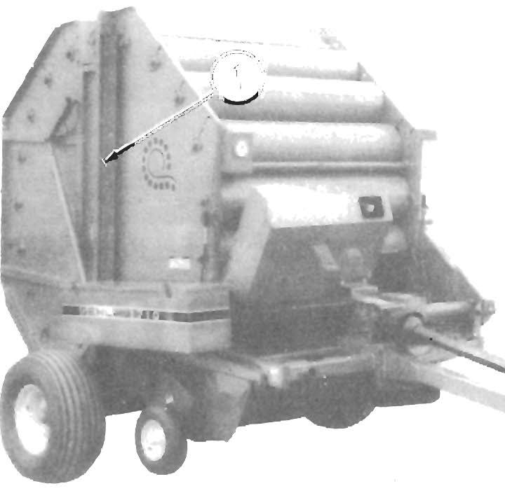
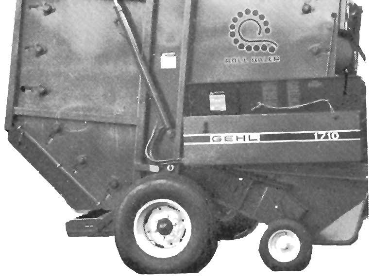
FUNCTIONAL DESCRIPTI ONS General (Fig. 6-1)
Crop material is picked off the ground by the FourTinebar floating Pickup and fed directly in t o the Baling Chamber. Chain-driven Rollers, located inside the Baling Chamber, roll and tumble the incoming crop into a round bale. Just before the bale reaches its final size, additional crop is fed into the Baling Chamber creating a bale with a medium density core and a hard outer shell. The hard outer shell helps to reduce settling and provides better weather resistance. Once the proper baling pressure is reached (as indicated by the RED area on the Pressure Gauge) the bale can be wrapped with twine and, by opening the Rear Door, ejected from the Baler.
Transmission of Mechanical Power
The minimum tractor power required to operate the Baler is 70 hp. The Baler Drawbar is vertically adjustable and MUST be properly connected to the tractor per details in the Preparing For Field Operations chapter. Mechanical power is transmitted from the tractor PTO, through a Telescoping PTO Driveline, a Rightangle Drive Gearbox, a Rubber Coupling, a Jackshaft, to the Main Drive Sprockets and Chain. The power is then transmitted by Chains and Sprockets to the (20) Rollers and the Pickup Assembly
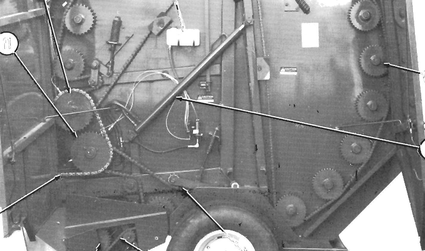
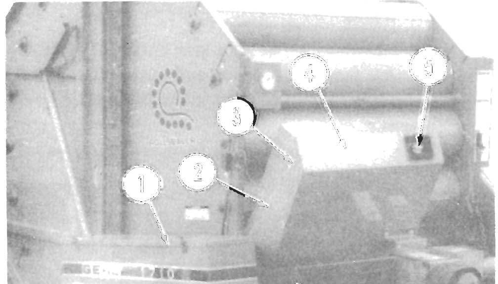
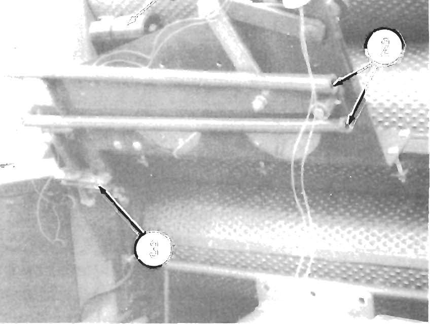
1 - Rear Door Connector Drive Chain
2
• Rear Door Rollers Drive Chain
3· Rear Door Cylinder Lock (each side)
4
• Roller Sprocket (1 of 20)
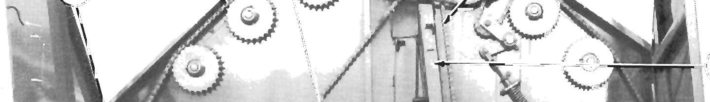
5
• Rear Door Hydraulic Cylinder (each side)
6
• Front Rollers Lower Drive Chain
7· Pickup Drive Chain
Density Control (Fig. 6-2)
Bale density is monitored by a Hydraulic Pressure Gauge which is located on the right front of the Baler. As the bale increases in size, it exerts more and more pressure on the Rear Door. The Rear Door is held closed by hydraulic pressure, supplied by the tractor to the Rear Door Cylinders. Since the Pressure Gauge is tapped directly into Rear Door hydraulic system, the Gauge indicates the amount of pressure required to keep the Door closed. Therefore, the Pressure Gauge is used as a guide to regulate bale density and, also, to indicate when to wrap and eject the bale.
NOTE: On units equipped with an Auto-Electric Twine Tie system, a Pressure Switch is also tapped into the Rear Door hydraulic system and is therefore regulated by the amount of pressure exerted on the Rear Door Cylinders . Refer to the Twine Tie Systems Functional Description later in this chapter.
Twine Tie Systems
The Manual-Electric and Auto-Electric Twine Tie Systems share many of the same components with the main exception being the Control Box, Switches and interrelated wiring.
In the manual system, control of the Electric Actuator (which, in turn, moves the Twine Tubes from side to side) is performed by the operator by toggling a Switch on the remote mounted Control Box. This feature is also available on the Auto-Electric system but, only while in MANUAL operating mode. In the AutoElectric Tie system (when operating in the "AUTO" mode) the entire wrapping and twine cutting operation is controlled automatically.
B---:----
Also included only in the Auto-Electric system is a Pressure Switch which activates the bale wrapping sequence when hydraulic pressure on the Rear Door Cylinders reaches a predetermined value (the Pressure Switch also activates an Alarm which signals the operator that the wrapping cycle has begun). In the Manual-Electric system, the operator must watch the Pressure Gauge and when it is at the required pressure, the operator must manually start the wrapping cycle. (Refer to the Density Control topic earlier in this chapter for additional information regarding the Pressure Gauge.)
Manual-Electric Control
The Manual-Electric Twine Tie System Control Box is provided with a single Switch which functions as follows:
Extend/Retract Switch on Control Box
A. Starting pressure (1000 to 2400 PSIG or more)
B. Bale forming pressure (1000 PSIG minimum)
C. Final pressure in dry brittle materials (3000 PSIG maximum)
D. Final pressure in normal damp materials (3200 PSIG maximum)
NOTE: GREEN Area = 1000 to 2000 PSIG RED Area = 2600 to 3200 PSIG
Fig. 6-2: Pressure Gauge
Transmission of Hydraulic Power
Hydraulic fluid pressure MUST BE provided by the tractor hydraulics system. The tractor's auxiliary control valve and remote control circuit are used to activate the Rear Door Cylinders (for raising and closing the Rear Door) and for holding the Rear Door closed during baling.
This Switch is a three-position, momentary contact, toggle-type Switch which returns to the "off" position when released. This Switch is provided to allow the operator to extend and retract the Electric Actuator, as necessary, for wrapping the bale with twine.
Move the Toggle to the right (and hold it there) to extend the Actuator Rod which, in turn, will move the Twine Tubes to the left; move the Toggle to the left (and hold it there) to retract the Actuator Rod which, in turn, will move the Twine Tubes to the right.
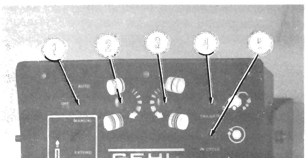
Auto-Electric Control (Fig. 6-3)
The Auto-Electric Twine Tie System Control Box is provided with various components which function as follows:
Auto/Off/Manual Switch
AUTO position - provides automatic operation of the wrapping System when the RECYCLE Button is pressed.
OFF position - disconnects electrical power to the Control Box (turns the Auto-Electric Twine Tie System "Off")
MANUAL position - provides for manual operation of the Actuator (enables the EXTEND/RETRACT Switch)
End-wrap Control
Turn the Knob on this Control clockwise to increase the number of twine wraps on the bale ends or counterclockwise to decrease the number of twine wraps on the bale ends.
Center-wrap Control
Turn the Knob on this Control counterclockwise to increase the number of twine wraps across the bale or clockwise to dec re ase the number of twine wraps across the bale.
Extend/Retract Switch
This Switch is enabled ONLY when the AUTO/OFF/MANUAL Switch is in the MANUAL position and is a momentary contact, toggle-type Switch which returns to the "off" position when released. This Switch is provided to allow the operator to manually extend and retract the Electric Actuator, when desired, and thereby override automatic control of the Actuator.
If the manual override is used and/or the automatic cycle is interrupted, the Actuator will return automatically to the fully extended position (and continue to cycle) when the RECYCLE Button is pushed.
Recycle (Pushbutton) Switch
This Switch is a momentary contact, pushbutton-type Switch which "starts" the wrapping cycle when pressed and returns to a "deactivated" position when released.
If it is desired to wrap the bale BEFORE the Bale Size Sensor Switch activates the automatic cycle, push and release the RECYCLE Switch Button; this will activate the System and automatically execute one wrapping cycle.
Horn
The Horn is provided to inform the operator that the bale has reached a predetermined size (determined by the setting of the Bale Pressure Sensor Switch) and that the wrapping cycle is about to begin. The Horn continues to sound until the Twine Tubes are in position and ready to feed twine into the bale chamber.
Circuit Breaker
1 - Auto/Off/Manual Switch
2 - End-wrap Knob
3 - Center-wrap Knob
4 - Tailgate Indicator

5 - In Cycle Indicator
6 - Extend/Retract Switch
7 - Power Harness Connection
8 - Circuit Breaker (Pushbutton)
9 - Baler Harness Connection
10 - Recycle (Pushbutton) Switch
Fig. 6·3: AutO-Electric Twine Tie Control Box
Tailgate Indicator
This Indicator is NOT in use on RB 1710 model Balers.
In Cycle Indicator
This Indicator will be "on" during the entire wrapping cycle and "off" all other times
A Pushbutton-type (resetable) Circuit Breaker is provided for protection of the Electric Actuator and Control Box wiring. Do NOT attempt to override the Breaker circuit by holding down on the Pushbutton. AL WAYS determine and correct the cause of the Breaker trip when resetting is required.
Baling Tips
The following information provides guidelines for using the Baler to get the most out of your crop and investment.
Preparing The Material For Baling
The material, to be baled, can be prepared in a number of different ways, depending on the operator's preference and available equipment. Except for windrow size, a general rule to follow is to prepare the material the same way as you would for rectangular baling.
The most desirable bales result when the material is prop e rly c ut and conditioned and then formed into even, full, Pickup - width windrows.
Cutting the C rop
Cut the crop as long as possible. Excessively dry, short, slippery and/or thin crops, as are sometimes enco untered in certain grasses and straw, can be successfully baled, providing that the material is of sufficient length to hold the bale together. However, when baling crops such as these, difficulties in building Gauge pressure above 2500 PSIG and in wrapping the bale with tw i ne at the end of baling cycle, may be exp e rienced, regardless of cut crop length. Refer to the Baling topic, later in this chapter, for more details.
C onditi oning the Crop
Over-conditioning the crop is NOT advisable, particularly if the bales are going to be stored outside, because excessive shattering of the stems will invite moisture absorption, which can lead to spoilage.
Under-co 'nditioning can also cause spoilage, particularly when baling cane-type crops and other heavystemmed materials.
NOTE: Proper conditioning can best be accomplished using either a self-propelled windrower or pUll-type mower conditioner.
Windrowing the Crop
Bales of consistently uniform size and density can best be produced by starting with windrows of proper size. Windrows should be reasonably even in height and width. Windrows with high center crowns result in more material in the center of the bale, producing a bale with loose ends and making it more difficult to wrap the bale with twine.
If full, Pickup-width windrows (48"-66") cannot be produced. the crop should be formed into windrows of 30" or less. Windrows between 30" and 48" wide should be avoided because. as the Baler operator crosses the windrow from side to side to crowd material into the ends of the Pickup. the center is being continuously fed and as a result, the bale will be barrelshaped with lower density at the ends and higher density at the center.
NOTE: If windrows are generally wider than the Pickup width (greater than 66''), installation of a Crowder Wheels Kit is recommended. Refer to the Optional Features &Accessories chapterfor additional information.
Baling
NOTE: To avoid damaging the Baler Drive Line, slow tractor RPM to 1400 or less BEFORE engaging PTO. Then, engage PTO slowly. In addition, NEVER disengage PTO quickly with a full bale in the Chamber. The mass of a rotating bale can cause a complete Drive Line reversal. When using a tractor equipped with a PTO brake mechanism, BE SURE to slow-down the engine speed BEFORE disengaging the PTO.
Use the following procedure as a guide for proper baling techniques.
1. After transporting the Baler to the field. adjust the Pickup height according to crop conditions and ground contour. Refer to the Pickup Height and Pickup Flotation topics in the Adjustments chapter of this manual. for details.
NOTE: The Pickup Assembly MUST be carried up off of the ground at all times. Operating with the Pickup too low to the ground, will result in excessive Tine wear or breakage and possible damage to the Pickup Strippers and Headers, Cams and Cam Bearings.
2. Move the Baler into position with respect to the windrow. Start the PTO, bring the tractor RPM up to the desired operating speed and begin baling.
3. Bale the driest crops first (usually the outside of the field) traveling in the same direction that the rake or windrower traveled so that the crop is picked up in a head-first position.
4. When baling hay in full, Pickup-width windrows. the average operating speed of the tractor should be approximately 4 to 6 mph. At this speed, the Pickup will gather the windrow into the Baler with the least amount of crop agitation.
5. When baling narrow windrows (30" or less). start forming the bale by driving down the center for approximately the first quarter of the bale. For the next quarter of the bale. weave back and forth across the windrow. so the crop is distributed evenly across the entire width of the Bale Chamber. Discontinue the weaving pattern for the last one half of the bale and concentrate on feeding the material. alternately, into the sides of the Pickup. The bales that are formed in this manner, are more uniform than bales that are formed by continuously weaving, during the entire baling cycle.