5 minute read
P REPARING FO R FIELD OP ERAT I ON

TRACTOR & DRAWBAR REQUIREMENTS
Tractor
The tractor, used to operate an RB1710 Baler, MUST have:
-a minimum of 70 PTO hp
-a 540 RPM PTO
- PTO and hitch dimensions conforming to the ASAE Standard
-a remote hydraulic output capable of powering a double-acting cylinder
-a minimum 60" (1524 mm) clearance between the insides of the tires (front & rear)
- an upright exhaust system (to help prevent a possible fire caused from sparks blowing into the windrow)
Awarning
Because dry material usually Is being processed, the tractor should also be equipped with Spark Arrestors to prevent starting fires.
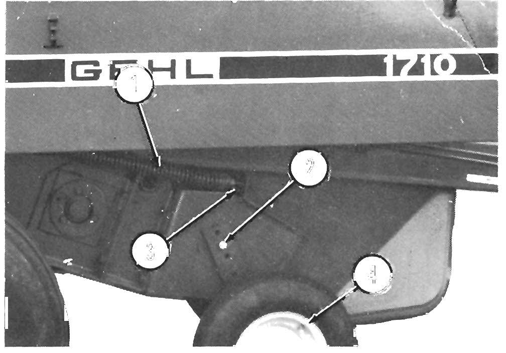
Drawbar Connection (Figs. 10-1 & 10-2)
Adjust the tractor drawbar to meet the ASAE Standard draw bar dimensions shown.
A Caution
The minimum distance, from the tractor PTO to the center of the hitch pin, MUST be 14" (355 mm) for 540 RPM to avoid damage to the Telescoping PTO Drive Shaft, when making sharp turns.
The Hitch Plate, bolted to the end of the Baler Drawbar, is reversible to enable attaching the Baler to a tractor equipped with either, a "low" drawbar [13-17" (330-430 mm) from the ground] or a "high" drawbar [17-21" (430-533 mm) from the ground].
To reverse the Hitch Plate, remove the mounting hardware and remount the Hitch Plate, as shown. When properly adjusted and attached to the tractor, the Baler Twinebox should be parallel with the ground or angled slightly to the rear.
1 - 14" (335 mm) - 540RPM
2 - 6-12" (150-305 mm)
3 - 13-17" (330-430 mm)
4 - Hitch Plate
Fig. 10-1: Drawbar Hitch Plate in "Low" Mounting Position __

1 - 14" (335 mm) - 540RPM
2 - 6-12" (150-305 mm)
3 - 17-21" (430-533 mm)
4 - Hitch Plate
Fig. 10-2: Drawbar Hitch Plate In "High" Mounting Position
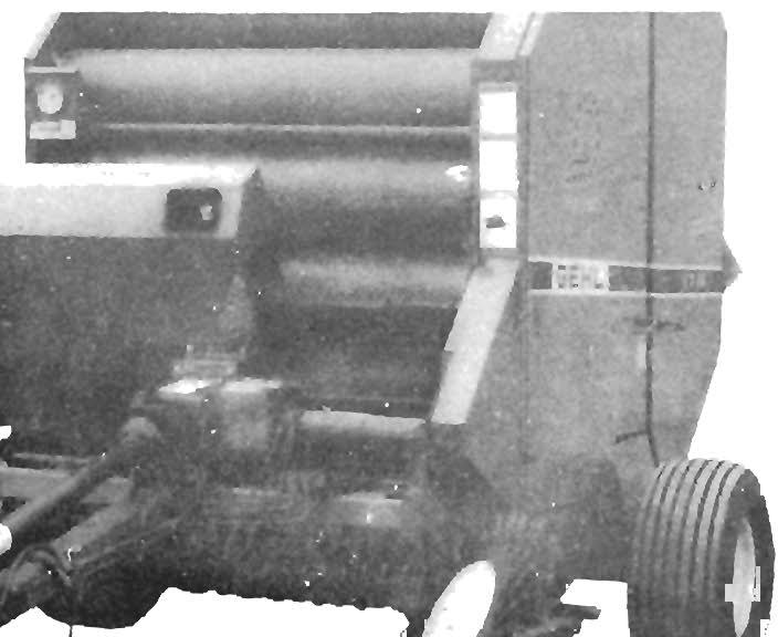
Attachment To Tractor
NOTE: If the tractor is equipped with a 3-point hitch, raise the lower arms to their maximum height (or remove them) to avoid interference with the Telescoping PTO Drive on the Baler.
A Caution
NEVER connect a 540 RPM Baler to a 1000 RPM tractor PTO. Check the RPM Warning Decal on the PTO Shield BEFORE connecting the Baler to the tractor.
Attach the Baler Drawbar to the tractor drawbar using a 3/4" or 7/8" diameter locking hitchpin that has a positive retaining device. To prevent crop material from catching on the hitchpin, it is recommended that the hitchpin be installed with the head-end down. After the connection is made, remove the Hitchjack and secure it to the "Storage Hub" on the side of the Baler Drawbar.
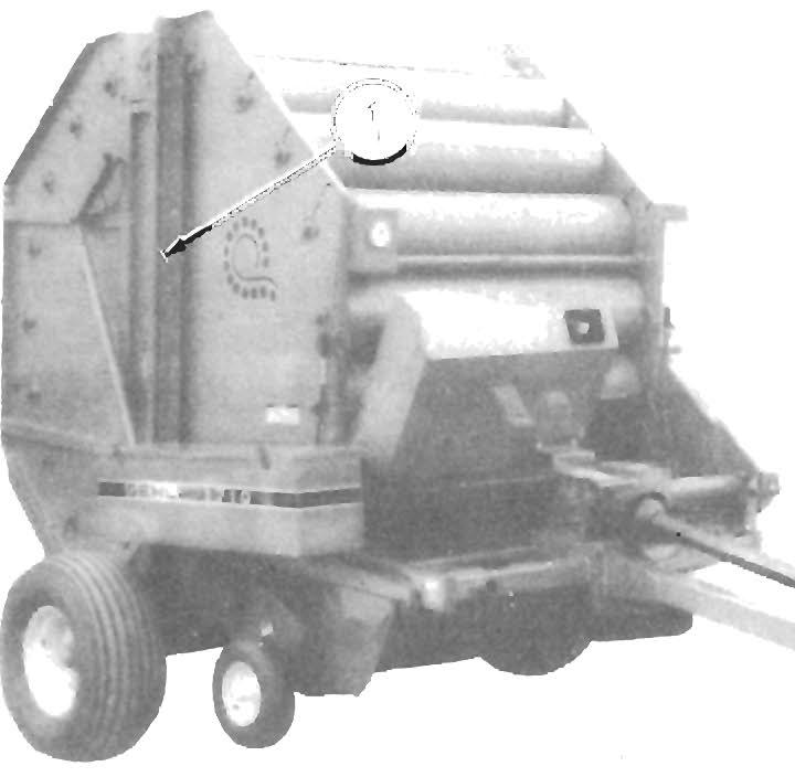
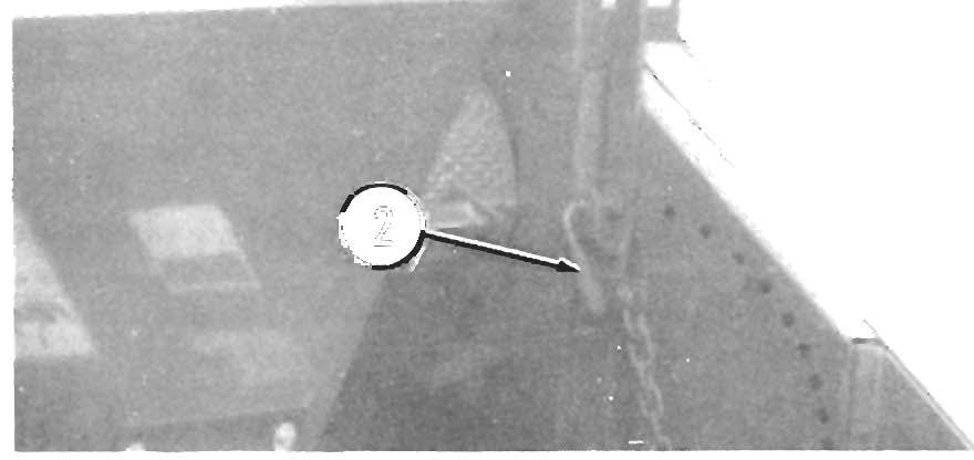
Drawbar Flap (Fig. 10-3)
If the Baler Drawbar is catching and bunching-up the windrow below the hitch, order and install Drawbar Flap (420-34054) to help eliminate the problem.
A Caution
The maximum Joint angle, whether In operation or not, MUST NOT exceed 80 degrees. Any angle greater than 80 degrees will result In damage to the Joint.
NOTE: AL WA YS orient and attach the PTO Drive with the CV end coupled to the tractor PTO shaft.
PTO Drives are provided with Spring-loaded Locking Devices on each end to positively lock the Drive connections onto the tractor PTO shaft and the Baler Drive Input Shaft. Depress the Locking Device, against the Spring tension, and slide the Yoke onto its respective Drive Shaft. Release the Locking Device and move the Yoke ahead or back until the Lock engages into the groove of its respective shaft.
Aw A Rning
1 - Drawbar Flap (420-34054)
Fig. 10-3
Telescoping PTO Drive (Fig. 10-4)
The Baler is equipped with a Wide-angle Constant Velocity PTO Drive Shaft. This constant velocity capability while cornering, results in a smooth, quiet running drive line, without power fluctuations.
Acaution
Maximum Joint angle, In continuous operation, Is limited to 35 degrees. Wide-angie constant velocity joints are NOT designed for use as angled-gearboxes. Any continuous operation at angles greater than 35 degrees, WILL result In shortening Joint life.
BEFORE starting the tractor engine, BE SURE that the PTO Yokes are positively engaged onto their respective shafts and that the Baler Drawbar Is securely connected to the tractor drawbar with a locking hltchpln. Also, BE SURE the tractor PTO shield Is In place and properly secured and that the Telescoping PTO Drive Shields are rotating freely. A
A 35' (maximum) In continuous operation 80' (maximum) at any time
Fig. 10-4: PTO Constant Velocity Joint
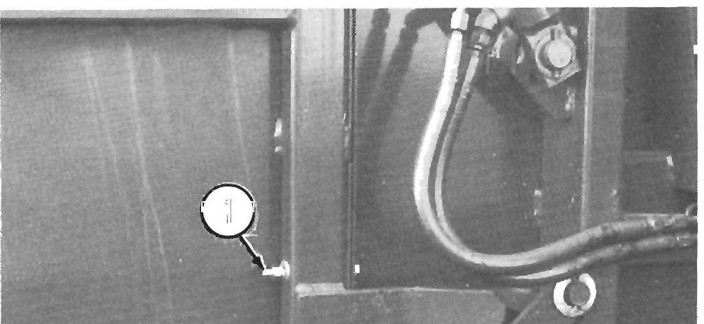
Hydraulic Connections
NOTE: The tractor MUST have a remote hydraulic output capable of operating the Rear Door, double-acting, HydrauliC Cylinders. If the Baler is equipped with an optional HydrauliC Twine Wrapping System, the tractor MUST have an additional remote hydraulic output, to operate the Twine Wrapping, double-acting, Hydraulic Cylinder.
Install the appropriate quick-disconnect fittings, to match your tractor connections, onto the Baler Hydraulic Hoses . The quick-disconnect fittings are to be purchased they are NOT provided with the Baler Use Loctite ,or equivalent pipe sealing compound, on the fitting threads.
Connect the Hoses to the proper tractor hydraulic outlets, start the tractor and operate the remote control valve(s), to extend and retract the Cylinder(s) several times, to purge the air out of the system.
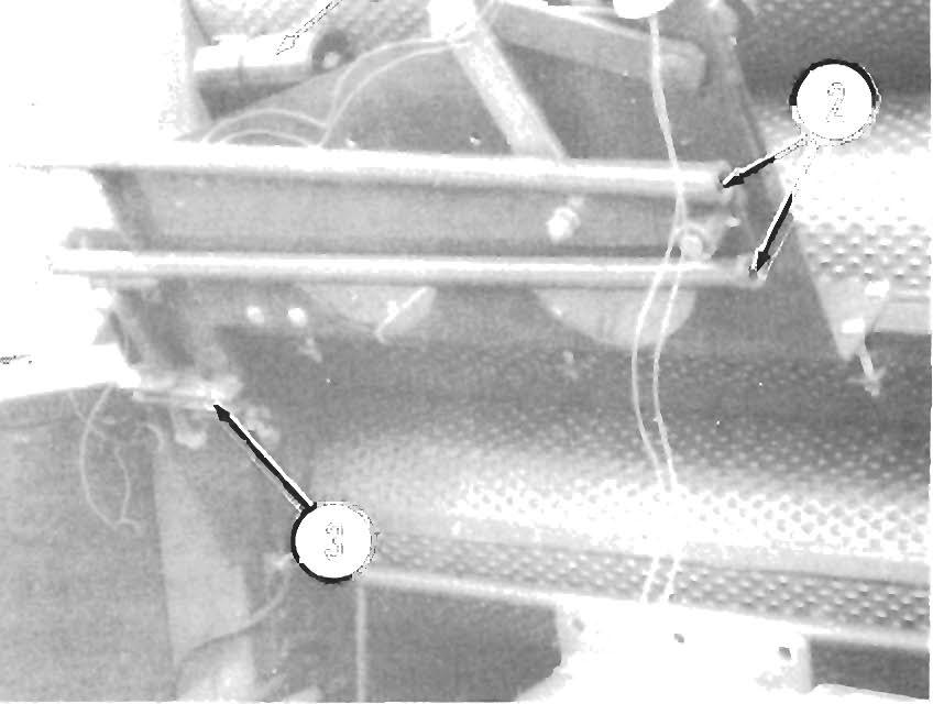
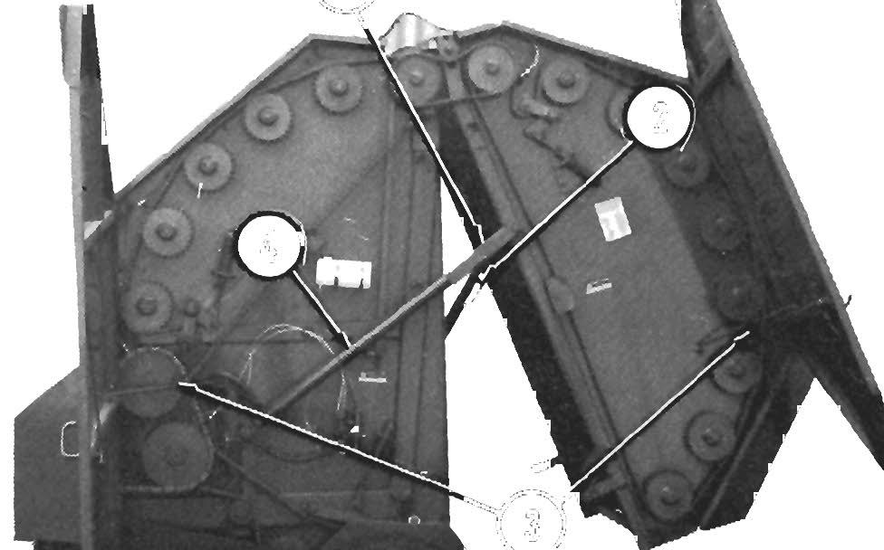
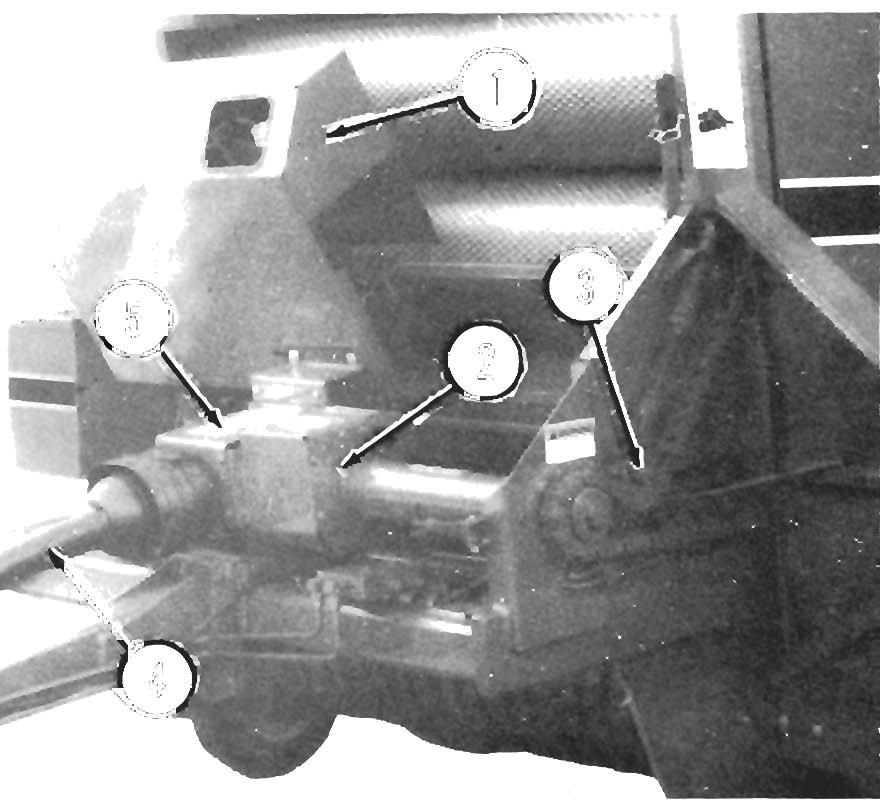
TWI NE ROUTING (Figs. 10-5 & 10-6)
To thread the Baler with twine, proceed as follows: Place up to four balls of twine in the Twinebox and tie the ends, if desired, for continuous feeding.
NOTE: ALWAYS tie the outside twine end of the first bal/ to the inside twine end of the next bal/, when placing twine bal/s in the Twinebox for continuous feeding.
First & S e con d Twine Ball Routing
Pull the end of the twine from the center of the first ball through the Front Guide on the Twinebox Cover, through the Lower Guide in the Twinebox Side and out to the Twine Tensioner, if used. From there, route the twine through the bushing in the side of the Twine Tie Guard and over to the Glass Guide on top of the Twine Tubes
NOTE: To help feed twine through the Twine Tubes, position them so they are in a vertical position. AI/ow about 12-18" of twine to extend from the Tubes before starting to bale. After the first bale has been tied and the twine cut, the twine (extending from the Tubes) will be held by the Clamp Jaws. The Jaws should provide an 18" tail of twine for starting to wrap the next bale.
Third & Fourth Twine Ball Routing
Pull the end of the twine from the center of the third ball, through the Rear and Center Guides on the Twinebox Cover, through the Upper Guide in the Twinebox side and out to the Twine Tensioner, if used. From there, route the twine the same as for the first ball, except route the twine through the other Twine Tube.
1 - Twine Box
2 - Twine (From Twine Box)
3 - Bushing

4 - Twine Tie Guard
5 - Glass Guide
6 - 18" Tall of Twine
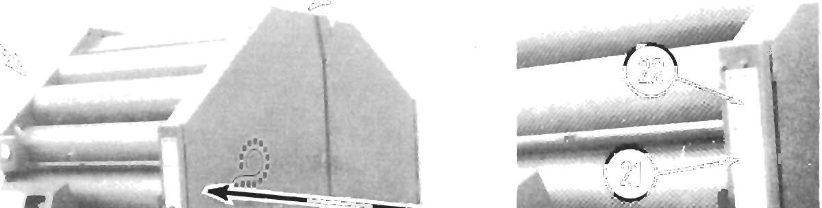
THROAT GUIDE BAFFLE (Fig. 10-9)
For improved performance when baling dry, short materials, like straws and grass hays, install the Throat Guide Baffle, supplied with the RB 1710 Baler. The Baffle is stored on the right side of the Baler behind the Pressure Gauge.
When installed, the Baffle prevents bale material from falling back out of the Bale Chamber, onto the rear of the Pickup Assembly. This will help prevent plugging at the rear of the Pickup area.
Adjust the Throat Guide Baffle for 1/16 inch clearance to the Roller outside diameter, as shown.