4 minute read
A C AUTION

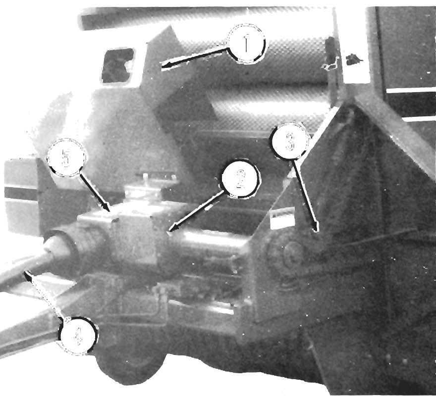
ONLY use the Throat Guide Baffle when baling very dry straw or short, dry grass hays The Throat Guide Baffle MUST be removed when baling damp to normally moist materials to prevent material build-up which can cause drive line loading and possible fire. Also, BE SURE to use BOTH Rear Door Cylinder Locks when Installing, removing or checking the Baffle. Improper Installation, adjustment or lise of the Throat Guide Baffle may cause a fire! Failure to heed, can result In personal Injury or machine damage.
To install the Throat Guide Baffle, proceed as follows:
1. Raise the Rear Door and engage BOTH Cylinder Locks. BE SURE that the Door is properly supported and that BOTH Cylinder Locks are in engaged.
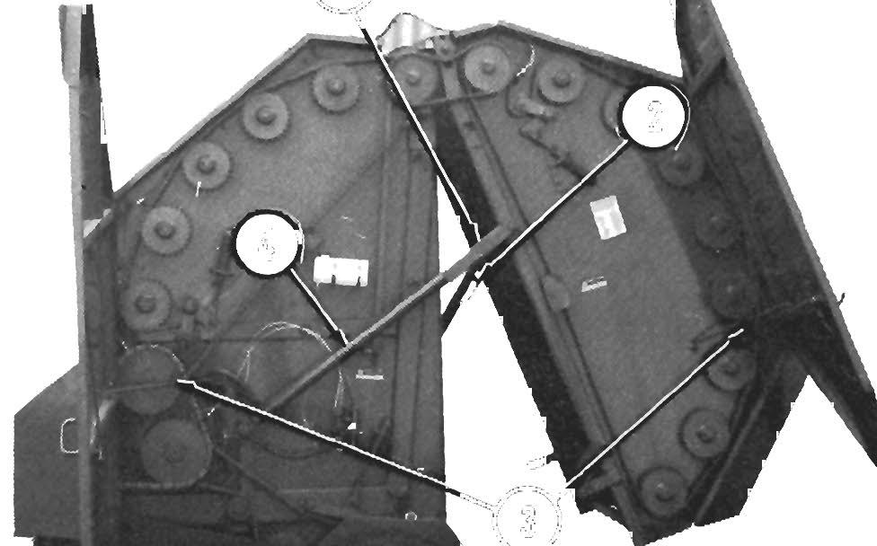
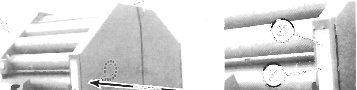
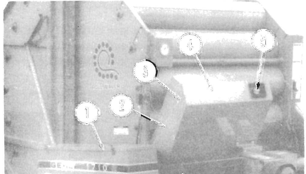
2. Position the Baffle so that there is 1/16" clearance between the edge of the Baffle Angle and the weld seam on the outside diameter of the 20th Roller (the 20th Roller is located just above the Baling Chamber Throat).
3. Once the proper positioning is obtained, secure the Baffle with the (4) 3/8 x 3/4 Tapping Screws provided. Holes are provided in the Baling Chamber Side Sheets for mounting the Throat Guide Baffle.
4. Test run the Baler, very slowly, to check for any rubbing. Repeat Steps 1 thru 3, above, if there is any indication of rubbing.
5. Raise the Rear Door, disengage the Cylinder Locks and lower the Rear Door.
DUAL-POSITION WHEEL AXLES
(Fig. 10-8)
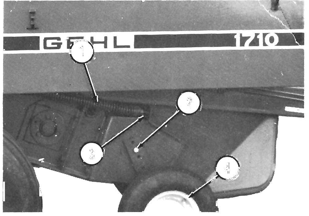
The RB1710 Baler is provided with dual-position Wheel Axles for making tread width adjustments. When the Baler is equipped with standard size tires (IlL x 14, 6-ply Implement Tires), the Axles should be installed with the 3/4-10 x 6-1/2" Bolts going through the inner mounting holes in the Axle Shafts.
When the Baler is equipped with wide, flotation tires (31 x 13.5 xIS, 6-ply Implement Tires) or when a wider tread width is desired (for hillside baling, as an example), the Axles may be installed with the 3/4-10 x 6-1/2" Bolts going through the outer mounting holes in the Axle Shafts.
Fig. 10-7: Throat Guide Baffle Detail (TypiCal)
1 • Outer Mounting Hole (For Wide Tires)
2· Inner Mounting Hole (For Standard Tires)
3 • Axle Shaft (1 each side of Baler)
4·3/4·10 x 6·1/2" Cap Screw, Nut & Lock Washer (1 each side of Baler)
Fig. 10-8: Dual-Position Axle
Trans P Orting
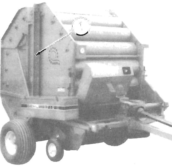
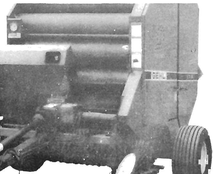
SMV EMBLEM & REFLECTORS (Fig. 11-1)

The Baler is provided with a Slow-moving Vehicle (SMV) Emblem Mounting Bracket on the left side of the Rear Door Upper Dust Panel. Red Reflector Strips are also provided on each rear corner of the Baler.
NOTE: Purchase the SMV Emblem locally. Also, because of variations in safety laws for different states and localities, it may be necessary to display the SMV Emblem in a different location. Your GEHL Dealer can assist you in relocating the Mounting Bracket, as necessary.
Fig.
Accessory Safety Chain (Installed)
A Cau T Ion
ALWAYS follow state and local regulations regarding use of a safety chain and auxiliary lighting when towing arm equipment on public highways. ONLY a safety chain (NOT an elastic or nylon/plastic tow strap) should be used to retain the connection between the towing and towed machine, in the event of separation of the primary attaching system. BE SURE to check with local law enforcement agencies for your own particular regulations. Unless otherwise prohibited, use a Slowmoving Vehicle Emblem.
PICKUP (Fig. 11-3)
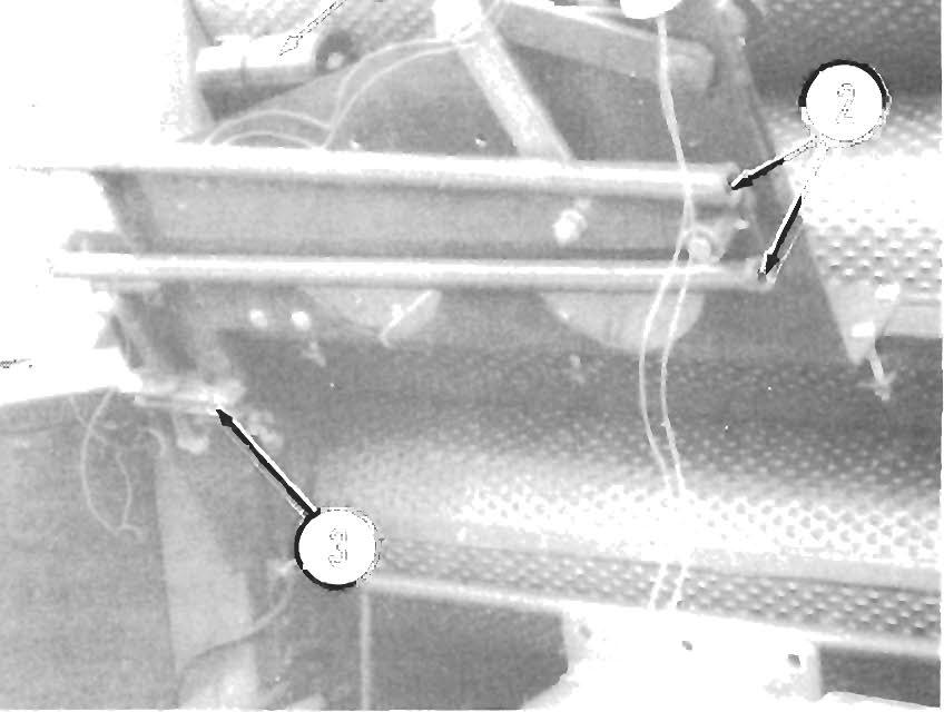
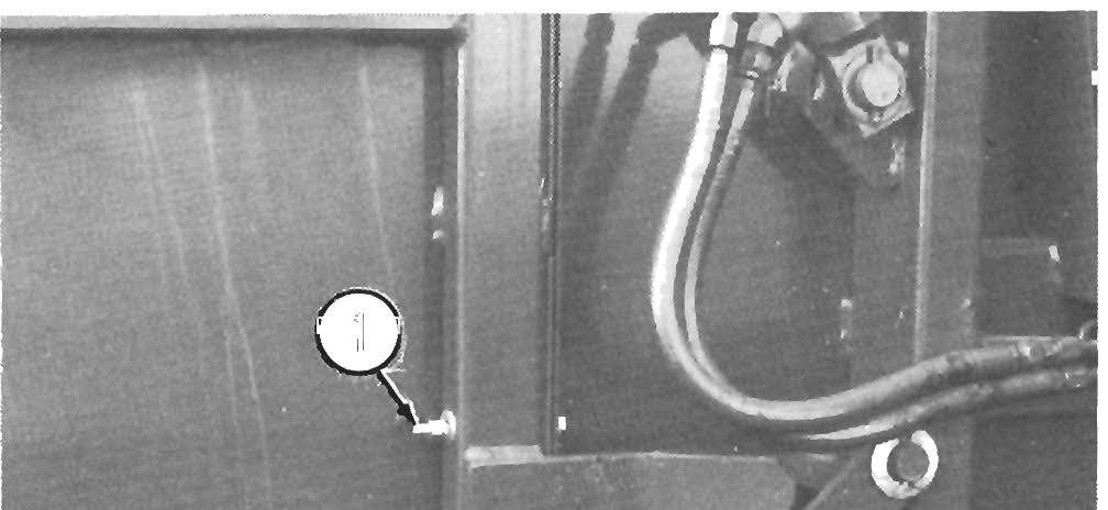
SAFETY CHAIN & AUXILIARY LIGHTING (Fig. 11-2)
As required or when desired, the Baler can be equipped with a safety chain for operation on public highways. The safety chain should be attached to the tractor and Baler as shown. When attached in this manner, the safety chain shoulq have the following characteristics:
- Chain is sufficiently slack to allow turns and movements of either the tractor or the farm implement, without placing tension on chain.
- Chain is of sufficient strength to hold the decoupled implement (and its load) and tow it to the shoulder.


Anytime the Baler is to be transported, BE SURE to raise the Picbp to the maximum height (transport position) using the Pickup Adjustment Lever. Secure the Pickup Lever using the Lock Chain provided.
T Roublesh Oo Ting
NOTE: This Troubleshooting guide presents problems, causes and suggested remedies beyond the extent of loose, worn or missing parts and It was developed with the understanding that the machine is In otherwise good operating condition. Refer to the Index at the back of this manual for Chapter and Topic page references. For additional assistance, BE SURE to contact you local GEHL dealer.
Problem
Automatic Chain Oiler over-oiling.
Automatic Chain Oiler under-oiling.
Miscellaneous Problems Cause
Sticky Check Valve.
Dirty Screen.
Oil too heavy.
Drive Chains overheating.
Lack of lubrication.
Chains and/or Sprockets misaligned.
Material Pickup
Pickup is NOT completely cleaning material off the field.
Windrow too heavy, with wet "slugs" .
Windrow too light.
Pickup set too high off of the ground.
Broken or missing Pickup Tines
Pickup NOT running or running too slow.
Pickup set too low to the ground.
Pickup mechanism jammed.
Pickup Drive mechanism worn.
Pickup Tines pulling oncoming material.
Pickup Tines running over oncoming material.
Pickup speed too fast for ground speed.
Pickup speed too slow for ground speed.
Remedy
Remove and c lean Check Valve.
Remove and clean Screen.
Replace with 1O-W oil or lighter.
Refer to the Lubrication chapter.
Realign the Sprockets . Refer to the Service chapter
Reduce windrow height, utilize full Pickup width and/or reduce ground speed.
Increase ground speed or increase windrow size by combining windrows.
Readjust Pickup to lower the setting. Refer to Adjustments chapter.
Straighten or replace Tines. Refer to Service chapter.
Readjust Pickup to raise the setting. Refer to Adjustments chapter.
Exercise the MANDATORY SAFETY SHUTDOWN PROCEDURE and remove jam.
Replace worn or damaged parts. Refer to Service chapter.
Slow from 540 RPM and/or increase ground speed.
Decrease ground speed and/or increase PTO to 540 RPM maximum.
Problem
Bale Appearance
Cause Remedy
Bale density on the end(s) is Improper placement of material along Rerake material into a proper width loose or the bale is edge of bale windrow or pull baler in a weaving barrel-shaped. fashion.
AUTO·ELECTRIC TWINE WRAPPING SYSTEM
Circuit Breaker trips-out Short circuit in wiring. Check for faulty Pressure Switch or a repeatedly. short circuit in the wiring for this Switch and replace faulty Switch or repair the wiring, as necessary
Bent or damaged Linkages
Check the Twine Tubes and Linkages for bent or damaged parts which may be o v erloading the Actuator.
Automatic "start" feature Faulty Pressure Switch or wiring. Using a jumper wire, connect the does NOT work. ORANGE Wire to ground; if the System "starts", the Switch is faulty.
Automatic "start" feature Pressure Switch Wiring damaged or Repair Pressure Switch Wiring a ctivating prematurely. shorting.
Auto-Electric Twine Tie Poor ground connection(s). Check wiring to battery and tractor System functions erratically. grounding for power circuit.
Corroded connections. Clean all Terminals and Connectors.
No response from Center Brown wire shorted out. Make sure that the Brown wire is Twine Wrap Knob. NOT pinched and/or that the Brown wire is connected to the Normally Open Terminal on the Twine Delay Switch.