CHAPTER 14 SET- UP & ASSEMBLY SHIPPING HARDWA RE (Figs. 14-1 & 14-2) NOTE: The RB 171 0 Baler is shipped from the fac
WHEELS & TIRES
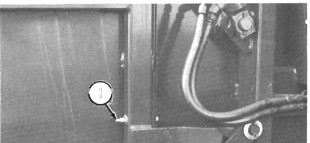
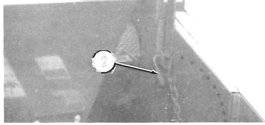
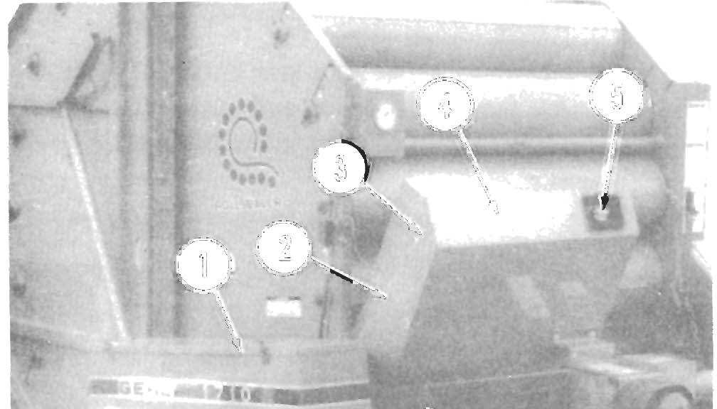
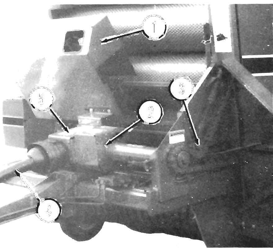
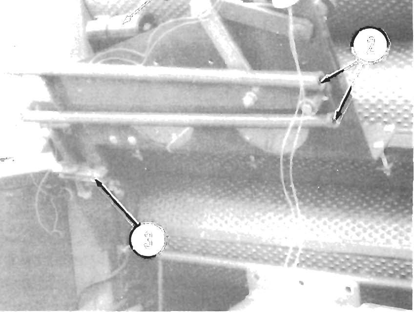
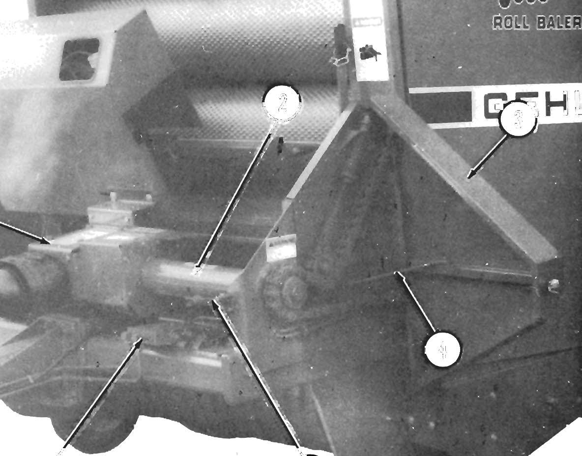
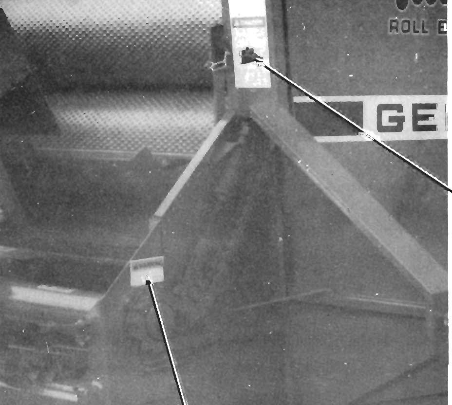
tory with the Rear Door bolted closed. BE SURE to remove the (2) Shipping Bolts (one on each side of the Baler, as shown), BEFORE attempting to open the Rear Door for the first time.
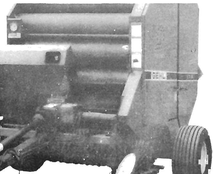
For transportation purposes, the RB 171 0 Baler may have been shipped from the factory without the Wheels and Tires mounted. If so, install the Wheels and Tires and tighten the Lug Nuts to 90 ft-Ib (124 Nm). Inflate the Tires to the pressure as listed in the Tire Pressures chart in the Service chapter.
NOTE:
TWINE TIE SYSTEM
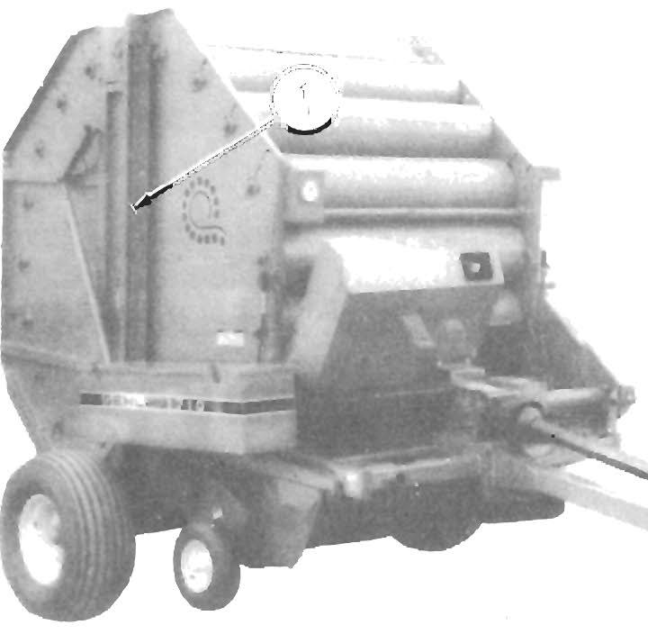
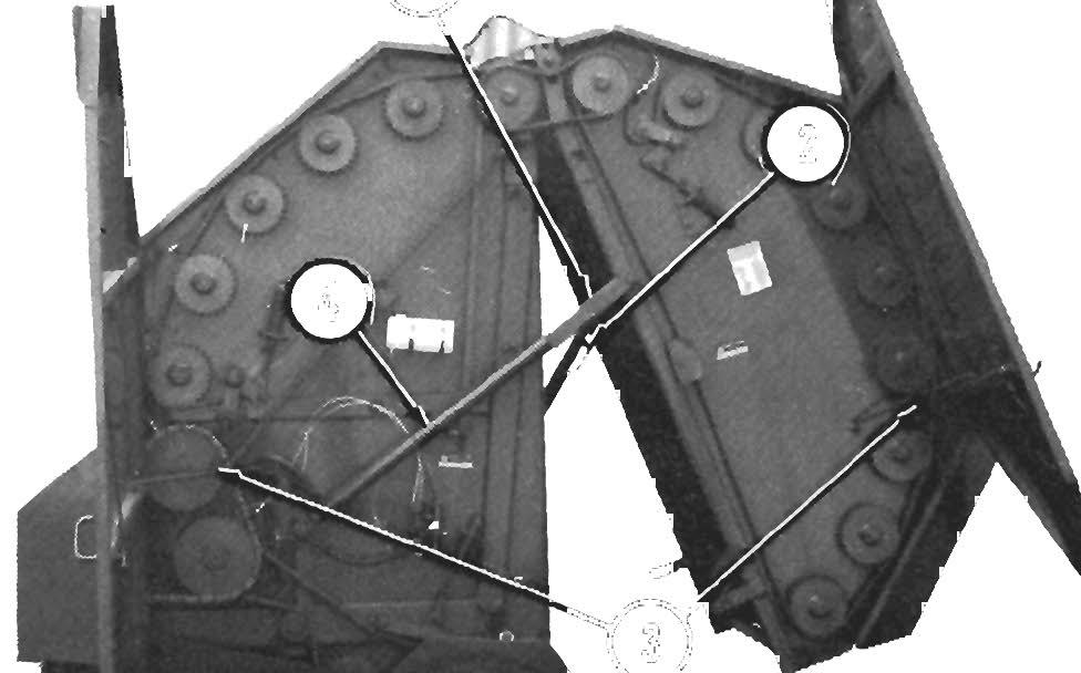
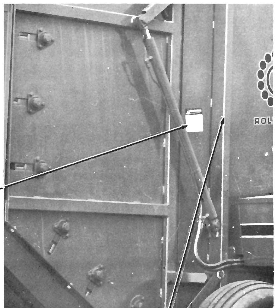
Some units may also be shipped with a Door Lock Bracket arrangement on the Door Handles of the two Large Hinged Doors on the left side of the Baler. These brackets are used to keep the Doors closed during shipment and should also be removed and discarded.
Manual-Electric-controlled Tie System
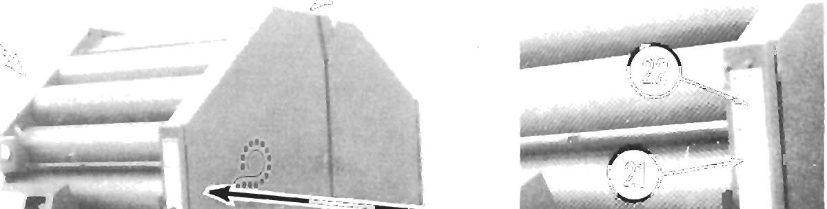
Power Cable Routing Make the Power Cable connection to the Plug on the Electric Actuator and route the tractor end connection along the Hydraulic Lines on the left side of the Draw bar, over the top of the Hitch Clevis and up toward the back end of the tractor. Install two (2) Nylon Tie Straps to secure the Power Cable to one of the Hydraulic Lines.
Tractor Control Box Installation A Bracket is provided for attaching the Receptacle onto the tractor. The Bracket should be located on the rear of the tractor in a position which prevents the Cable from being caught by the PTO. 1 • Shipping Bolt (Installed)
Fig. 14·1: Rear Door Shipping Bolt (Right Side)
Appropriate hardware and mounting brackets are provided for attaching the Control Box to a non-sup portive member (such as the cab or a fender) on the tractor. BE SURE to locate the Control Box within convenient reach. Make the Red (+) 12-volt and White (-) 12-volt tractor battery/ground connections for powering the Control Box.
Auto-Electric-controlled Tie System
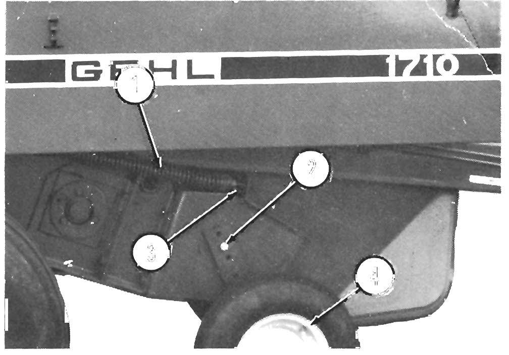
Control Box (Fig. 14-3) 1.
If NOT already preassembled, install and secure (3) Magnets (067040) to the bottom of the Mount ing Bracket (088345) using (6 each) #10-24 x 1/2 Round Head Machine Screws, Lock Washers and Nuts.
2.
Secure the Control Box (088340) to the Mounting Bracket (088345) using the (2) M8-1.25 Nuts provided.
3.
Set Control Box and Bracket Assembly aside.
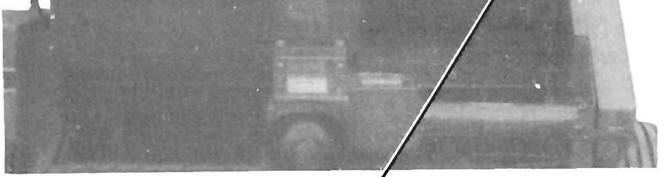
1 • Shipping Bolt (Installed)
Fig. 14·2: Rear Door Shipping Bolt (Left Side)
53