CHAPTER 9 SE RVICE GENER AL INFO RMATION
A CAUTION BEFORE starting to do ANY Service routines on this unit, exercise the MANDATORY SAFETY SHUTDOWN PROCEDURE (page 8).
The Bearing can be removed from the Shaft by loosen ing the Set Screw and then tapping on a punch, which is placed in the drift pin hole, to loosen the Collar. Install Bearings with self-locking Collars in the fol lowing manner:
1.
Place the Bearing and Collar on the Shaft with the cam surfaces next to each other. Tighten the bolts on the Bearing Retainers.
2.
Mate the cam, of the Lock Collar, with the cam, of the Bearing inner ring.
3.
Press the Lock Collar against the Bearing's wide inner ring cam and turn it, in the direction of Shaft rotation, until it tightly engages. Tighten the Collar further, by tapping on a punch inserted in the drift pin hole.
NOTE:
The following information is also referredto in the Troubleshooting chapterofthis manual. It should be understood that all services, detailed in this chap ter, are Owner-Operator responsibilities. Where indi cated, certain service routines should only be carried-out by (or under the direction of) an authorized GEHL Dealer or GEHL Company representative.
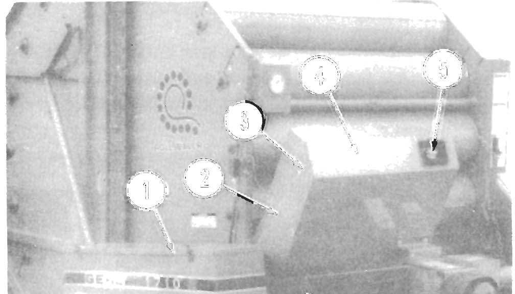
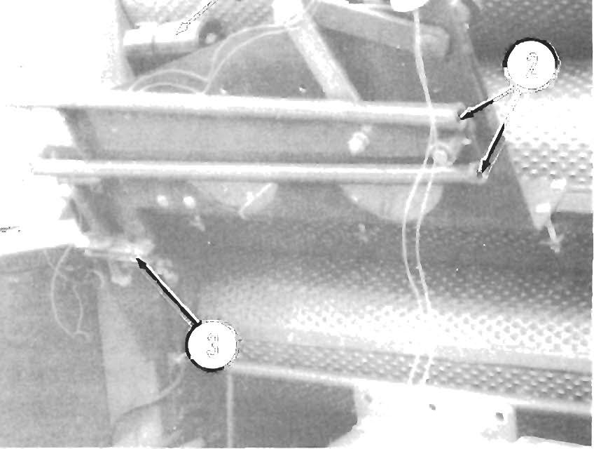
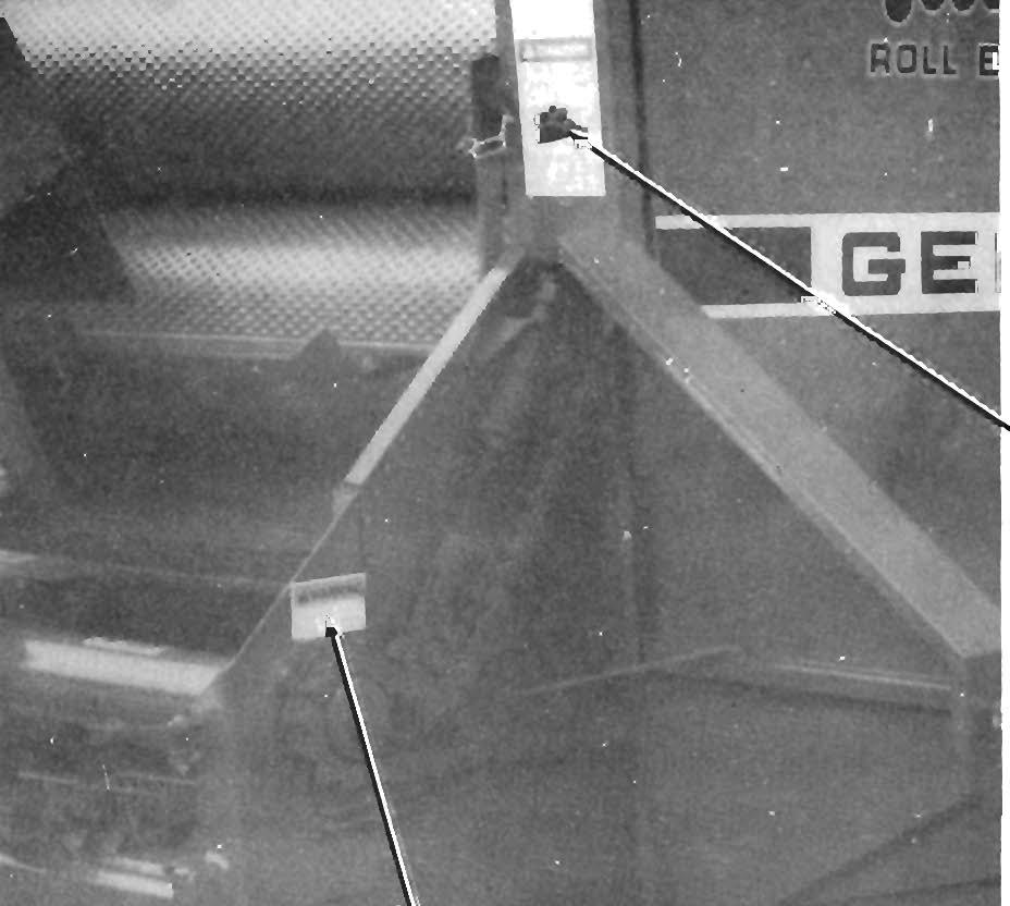
Sealed Ball Beari ng Replacement (Fig. 9-1)
NOTE: To avoid damaging the Lock Collar, do NOT overtighten it.
Sealed Ball Bearings are used on ·various Shafts on the Baler. This type of Bearing is generally retained with a Self-locking Eccentric Collar. The Lock Collar has a counterbored recess, which is eccentric with the Collar bore. This eccentric recess engages or mates with an eccentric end of the Bearing inner ring, when the Bear ing is assembled on the Shaft. The Bearing is engaged, on the inner ring cam, by the Collar. This assembly grips the Shaft tightly with a positive binding action that increases with use. The Collar Set Screw provides supplementary locking.
4.
Tighten the Set Screw in the Lock Collar.
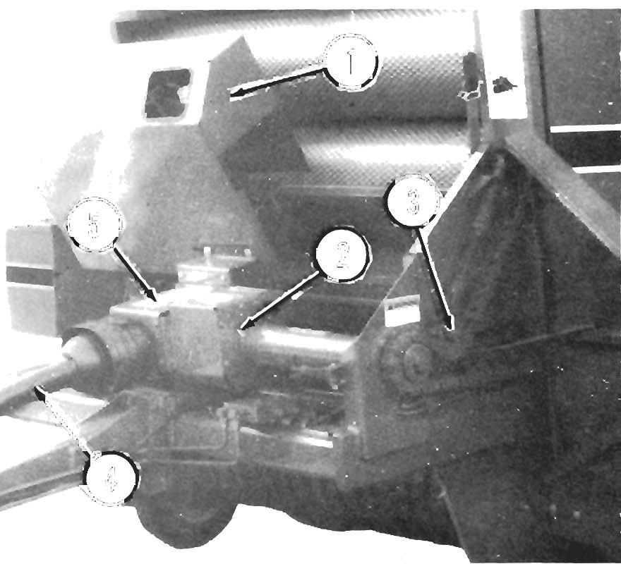
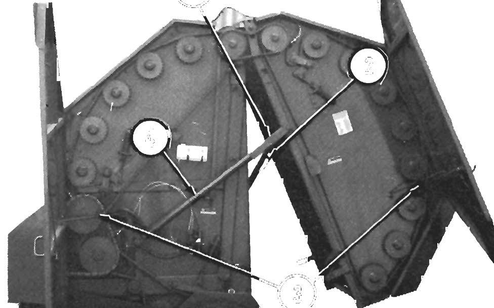
Gib Key The Gib Key, a tapered key with a tang on the thick end, is a combination locking device and hub retainer. The Gib Key will lock the hub in place and retain it from turning. The hub MUST have a matching tapered keyway for use with the Gib Key.
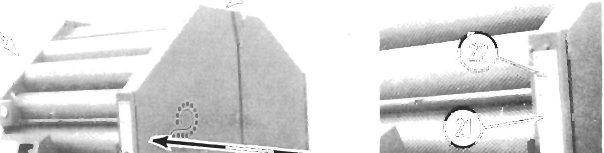
Removal (Fig. 9-2) 1.
Remove paint from the Shaft on both sides of the hub.
2.
Loosen the Set Screws.
3.
Drive hub away from Key head, using a large punch or drift. Make sure that Gib Key does NOT move with hub.
4.
Pull Key, using a pinch bar or tapered punch.
5.
Slide hub from Shaft.
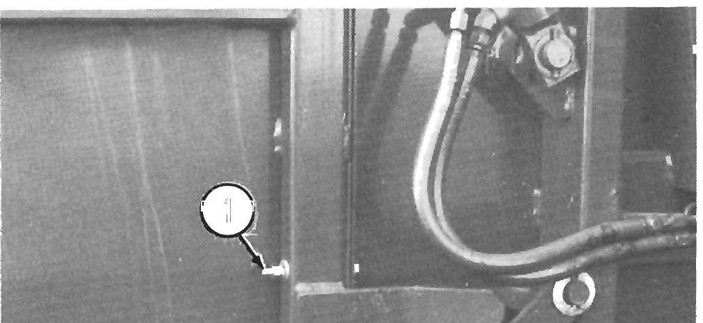
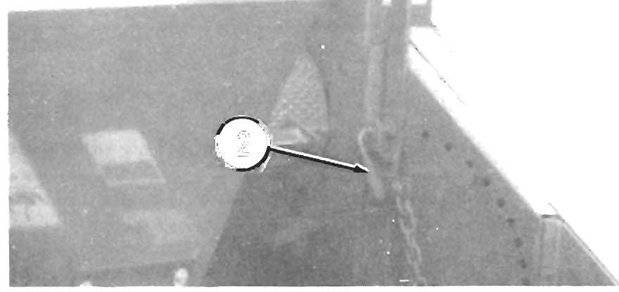
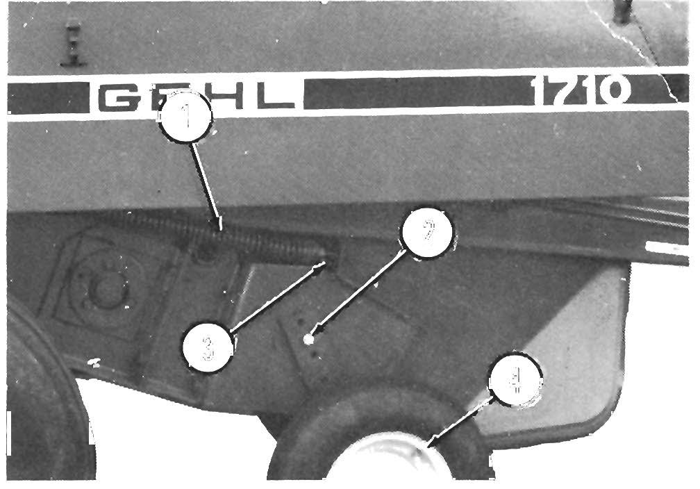
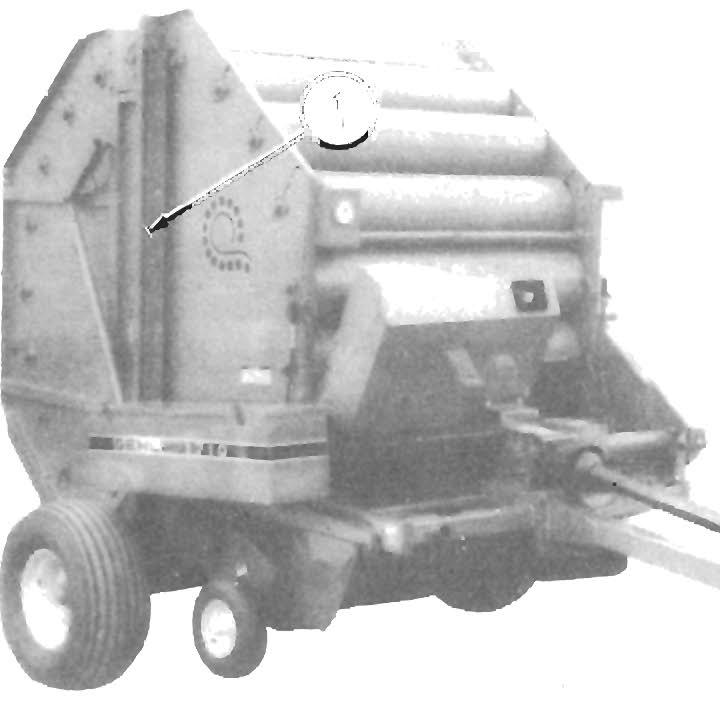
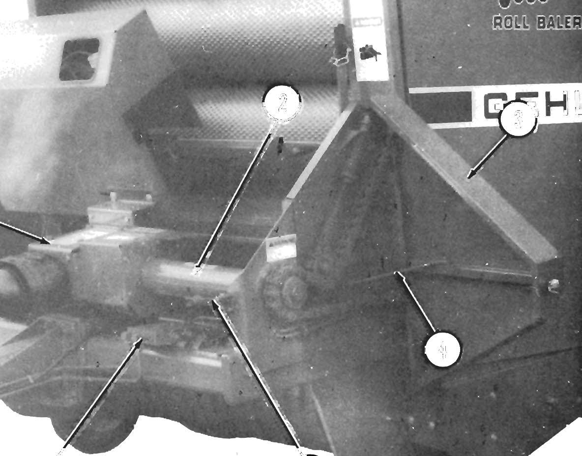
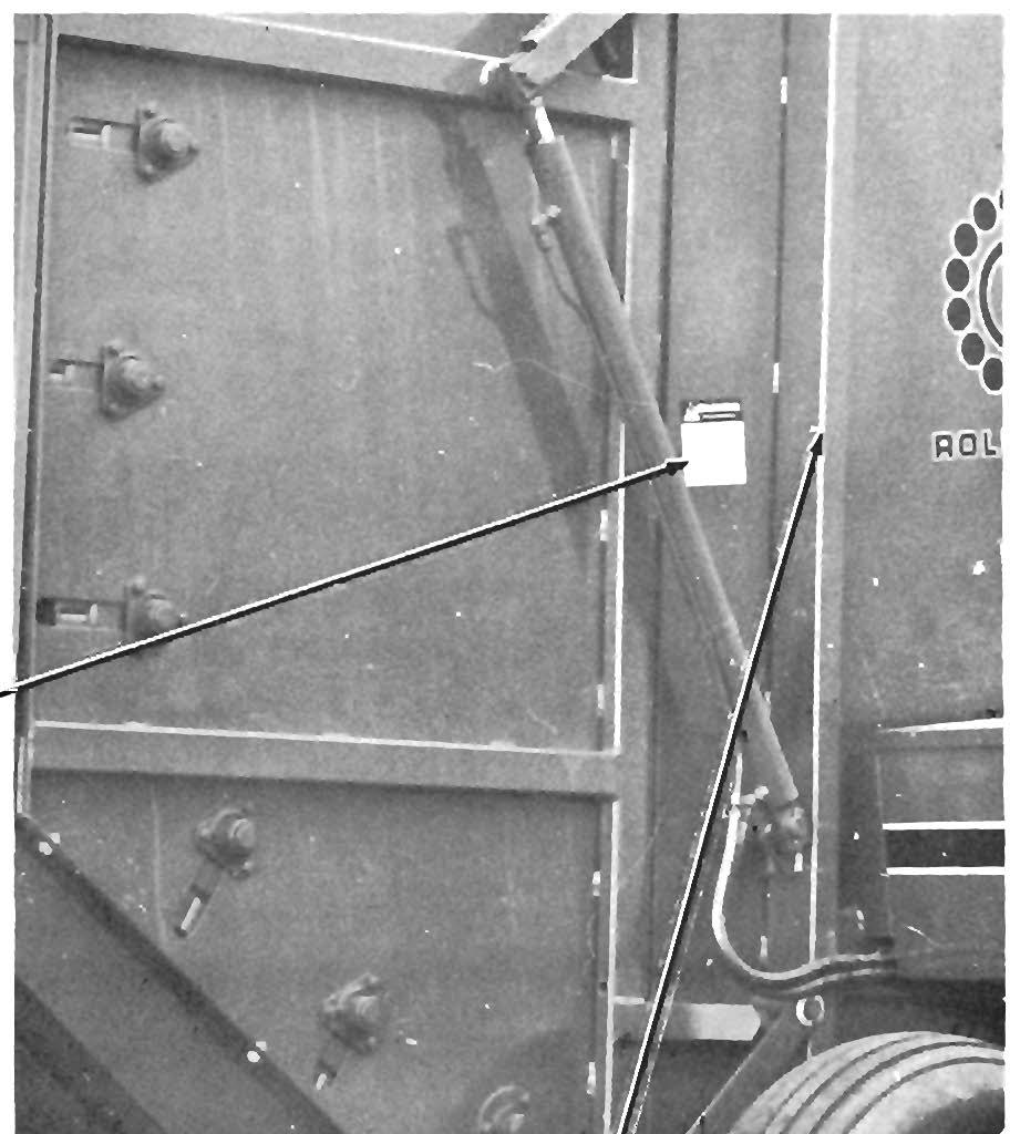
Installation (Figs. 9·3 & 9·4) 6.
Align Sheave or Sprocket and place Key in keyway.
7.
Reseat Key with a lead-headed hammer (or rub ber mallet), without moving Hub on Shaft.
1 - Bearing 2 - Setscrew 3 - Wide Inner Ring Cam 4 - Eccentric Self-locking Coliar
5 - Drift Pin Hole 6 - Counterbored Recess
Fig. 9·1
NOTE:
The Key does NOT have to be driven ex tremely hard, in order to hold.
37