CHAPTE R 7
ADJUSTM ENTS The Baler has been designed and factory adjusted to function properly under most field operating condi tions. However, due to the wide range of operating conditions encountered, some additional readjust ments may be required.
A CAUTION BEFORE proceeding to perform any adjust· ments on this unit, exercise the MANDATORY SAFETY SHUTDOWN PROCEDURE (page 8).
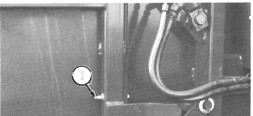
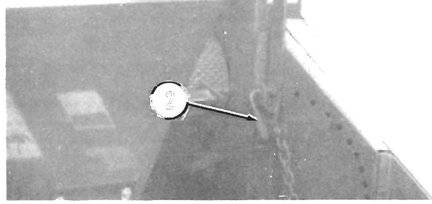
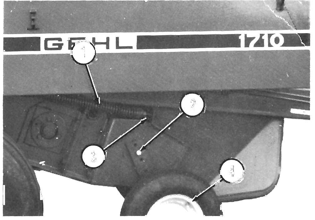
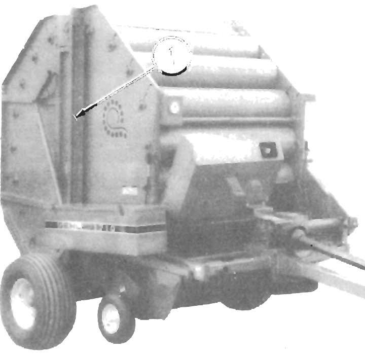
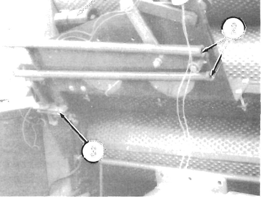
PICKUP HEIGHT (Fig. 7-1) NOTE:
The Baler Pickup should ALWAYS be run as high above the ground as possible while still being able to pick up all of the crop.
A Pickup Lever mechanism is provided on the left side of the Baler for raising and lowering the Pickup to make operating height adjustments.
NOTE:
A small Chain is provided on the left side of the Baler to lock the Pickup Lever when it is in the fully raised "transport" position. BE SURE the Chain is slipped over the end of the Pickup Lever whenever the Baler is being transported to ensure that the Pickup will remain in the raised position.
1 - Lock Chain 2 - Pickup Height Adjustment Lever 3 - Pickup Lever Latch Rod
Fig. 7-1
30
To raise or lower the Pickup, pull out on the Pickup Lever Latch Rod and then move the Pick up Lever over the hole in the Side Sheet, nearest to the desired posi tion. Release the Latch Rod while making sure the end of the Rod engages into the hole to lock the Pickup Lever at the desired setting. If the Baler is going to be transported, move the Pickup Lever to the top position and secure it with the Lock Chain.
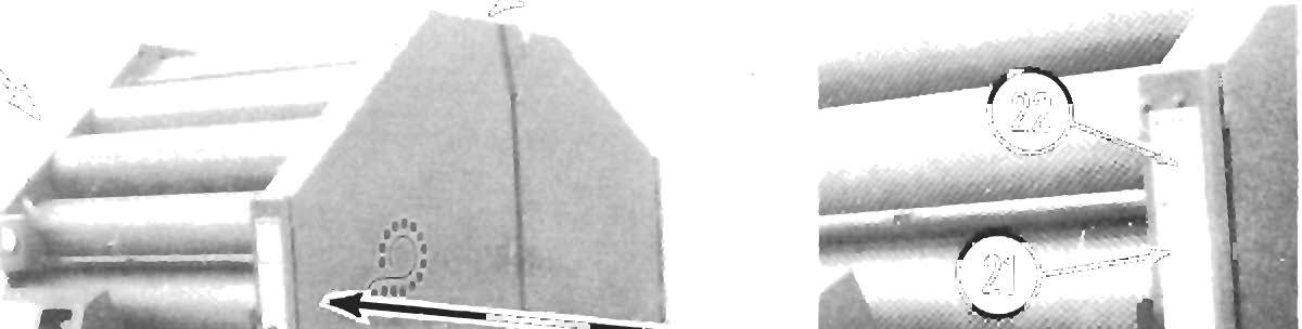
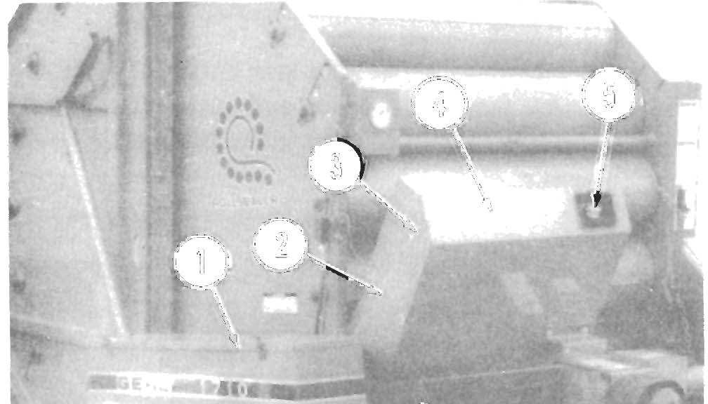
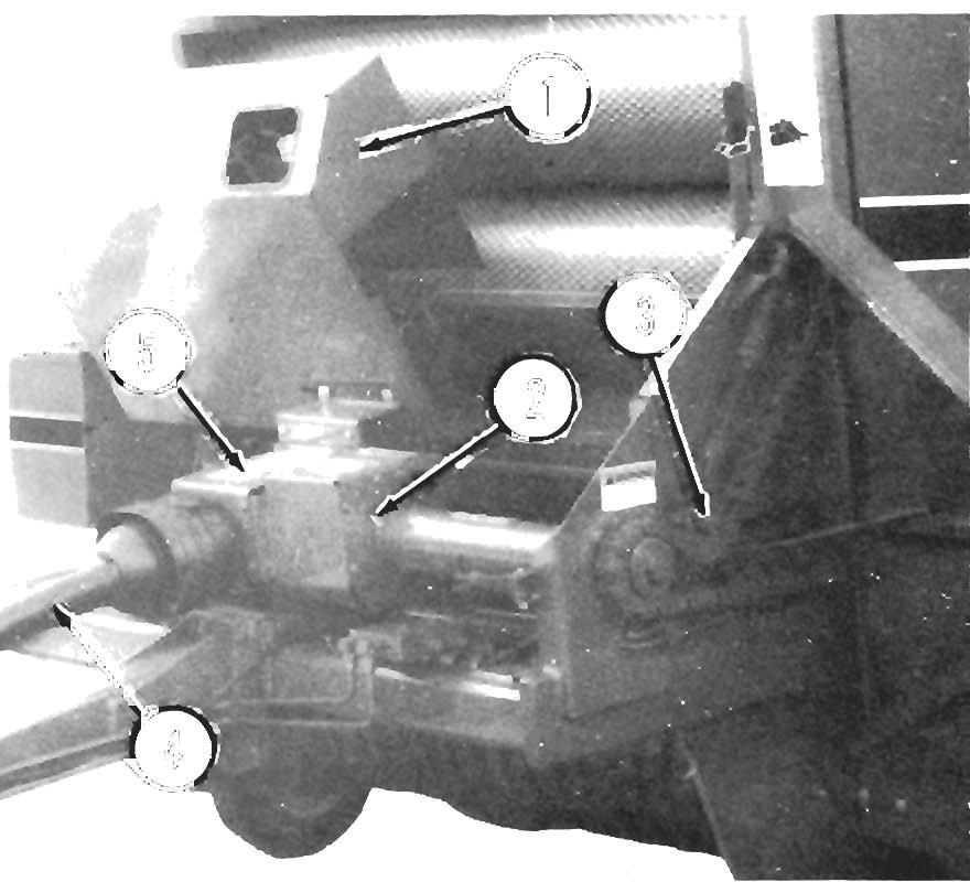
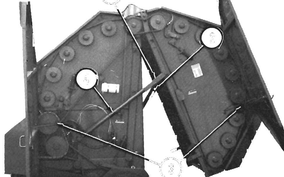
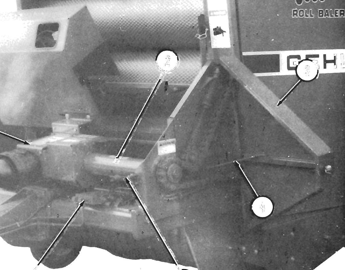
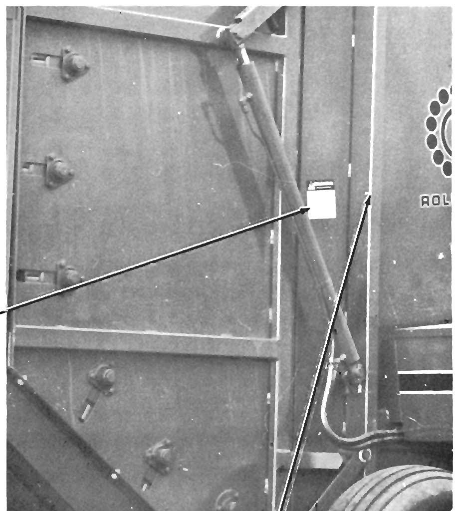
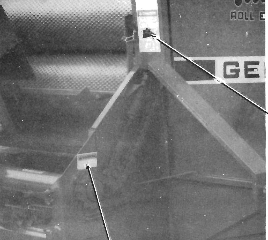
PICKUP FLOTATIO N (Figs. 7-2 & 7-3) NOTE: Proper flotation is determined with the Pick up in the "Iowered" position and with the Ora wba r Hitch Plate adjusted so that the Twinebox is parallel with the ground. The Baler is provided with a tension adjustable, float ing Pickup. For normal operating conditions on rela tively smooth ground , the recomm e nded Pickup Flotation Spring tension is approximately 30 pounds (14 kilograms) of lift required at th e cross pipe on the Hay Hold-down. For extremely rocky or rough groun d conditions, in crease Pickup Flotation Spring ten sion to allow the Pickup to float easier. To increase Spring tension, proceed as follows:
NOTE:
Measure the length of the Springs, BEFORE making any adjustments, so that the Pickup can later be restored to the initial setting. Also, make sure to adjust BOTH Springs equally.
1 - Pickup Flotation Spring (Right Side) 2 - 1/2" x 1-3/4" Cap Screw, Lock & Plain Washers (1 of 2) • Accessory Gauge Wheel Mounting 3·1/2" Tap Bolt & Hex Nut 4 • Accessory Gauge Wheel
Fig. 7-2
)