Unplugging
A DAN G ER DO NOT attempt to unplug the Pickup area while the PTO Is engaged. In addition, NEVER attempt to manually clear debris or foreign matter from any other part of the Baler, while It is running. Failure to heed, could result In death or serious bodily Injuryl ALWAYS exer cise the MANDATORY SAFETY SHUTDOWN PROCEDURE (page 8) BEFORE attempting to unplug the Pickup or manually clear debris from It! If plugging occurs between the Pickup and Baling
Chamber and/or the Pickup Drive Clutch is slipping, STOP forward travel IMMEDIATELY and disengage the PTO. Then, reduce engine RPM and re-engage the PTO. This will normally clear the Pickup. If NOT, repeat this sequence, as necessary, to clear the plug. If repeating this sequence, several times, does NOT clear the plug, open the gate and eject the bale, because the ratchet clutch will NOT drive pick-up backwards. If the plug still does NOT clear, exercise the MAN DATORY SAFETY SHUTDOWN PROCEDURE (page 8) BEFORE leaving the tractor to remove the plug by hand. When resuming Baler operation, adjust the ground travel speed; a slower speed may be required in heavy crops. In some conditions, it may also be necessary to remove one or both of the Springs on the Hay Hold down, to improve feeding. If plugging continues, check all of the Pickup Strippers to make sure that they are parallel and evenly spaced. Also, check the angle of the Baler to make sure that the Twinebox is parallel to the ground. If desired or as required, readjust the Hitch Plate to change the Baler angle so that the Twinebox is parallel to the ground or angled slightly to the rear. (Refer to the Preparing for Field Operation chapter for more details.)
NOTE:
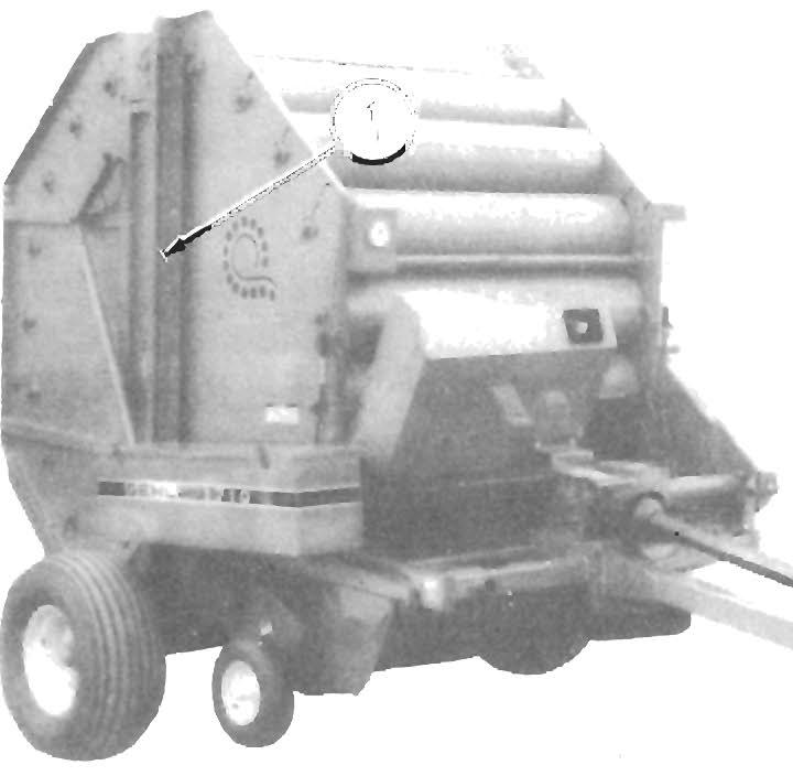
Do NOT allow any stones or other debris to enter the Baler or damage to internal parts may result. If a foreign object is seen entering the Baler, IMMEDI A TEL Y disengage the PTO to stop the Baler, open the Rear Door approximately 8" (or just enough to allow the object to pass through) and then slowly re-engage the PTO. After the object falls out, close the Rear Door and resume baling.
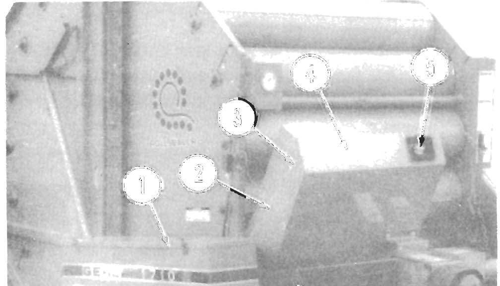
Using The Pressure Gauge For Density Control (See Fig. 6-2) In order to produce dense, uniform, 72-inch diameter bales, a minimum of 1000 PSIG of pressure MUST be maintained on the Rear Door, throughout the entire baling cycle. A Pressure Gauge is provided on the Baler to monitor the amount of pressure being applied to the Rear Door. Watch the Gauge as you are baling and maintain the pressure at 1000 to 2400 PSIG, (in the GREEN area or above), during the entire baling cycle. As the bale starts reaching its final size and density, the pressure will increase from its previous (more sta bilized) indication. When the Gauge Indicator reaches 2600 to 3200 PSIG, (the RED area), the bale is formed and ready for wrapping with twine.
NOTE: In some dry and/or brittle materials, it may NOT be possible to reach the final bale pressure (the RED area on the Pressure Gauge).
A CAUTION NEVER allow the baling pressure to exceed 3200 PSIG (above the RED area on the Pres sure Gauge). Baling at too high a pressure places excessive strain on the entire Baler and can cause Drive Chain failure.
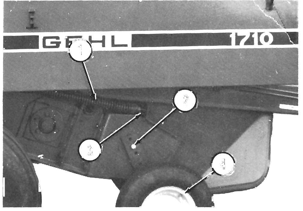
Wrapping Bale With Twine (Fig. 6-4 & See Fig. 6-2) The bale can be wrapped with twine any time after the mass of material in the Bale Chamber starts rolling. Usually, the bale should be wrapped only after the Pressure Gauge Indicator is in the RED area (2600 to 3200 PSIG). Refer to "Using The Pressure Gauge For Density Control" topic above, for details regarding baling pressures.
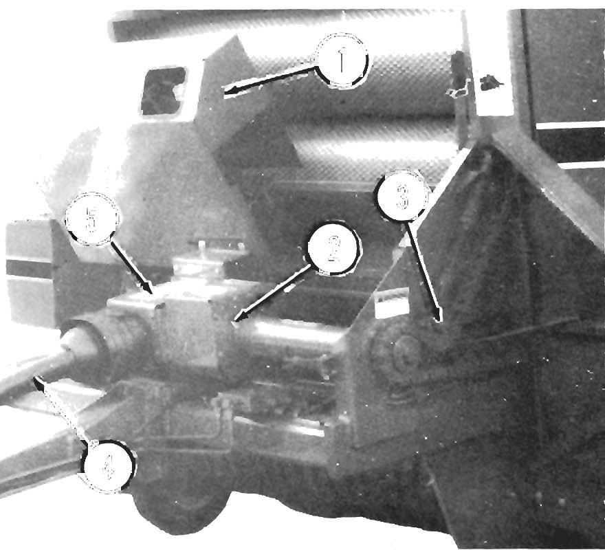
NOTE: The following procedure is the MANUAL sequence which is accomplished automatically by the Auto-Electric Tie system and activated automatically by a Pressure Switch. The entire process of wrapping the bale with twine is done from the tractor seat. The position of the Needle on the Hydraulic Pressure Gauge can be used as a fairly accurate guide for deter mining when to stop baling and start wrapping the bale with twine. When the desired pressure is reached, stop Baler forward travel. Then, using the Toggle Switch on the Control Box, activate the Actuator to position the Twine Tubes so they are centered and vertical.
25