A WAR NING BE SURE that the PTO Shafts and Connec· tlons are free to rotate Inside the Shields BEFORE starting the tractor engine!
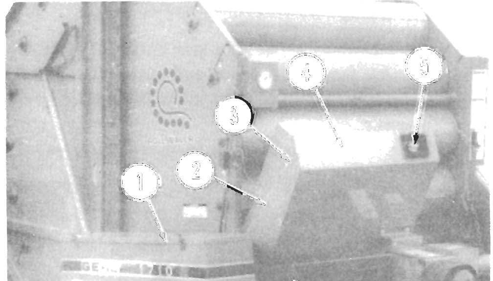
Gearbox & Jackshaft Shields (See Fig. 5·1) The Gearbox and lackshaft Shields are bolted in posi tion and MUST remain securely fastened, except for servicing.
Main Drive Shield (See Fig. 5·1) This hinged Shield, which is held closed by a Latch, covers and protects the front section of the Main Drive Chain mechanism. A Holder Rod is provided with the Shield to hold it open while servicing or making ad justments inside. BE SURE to keep the Shield closed and latched whenever the Baler is in operation.
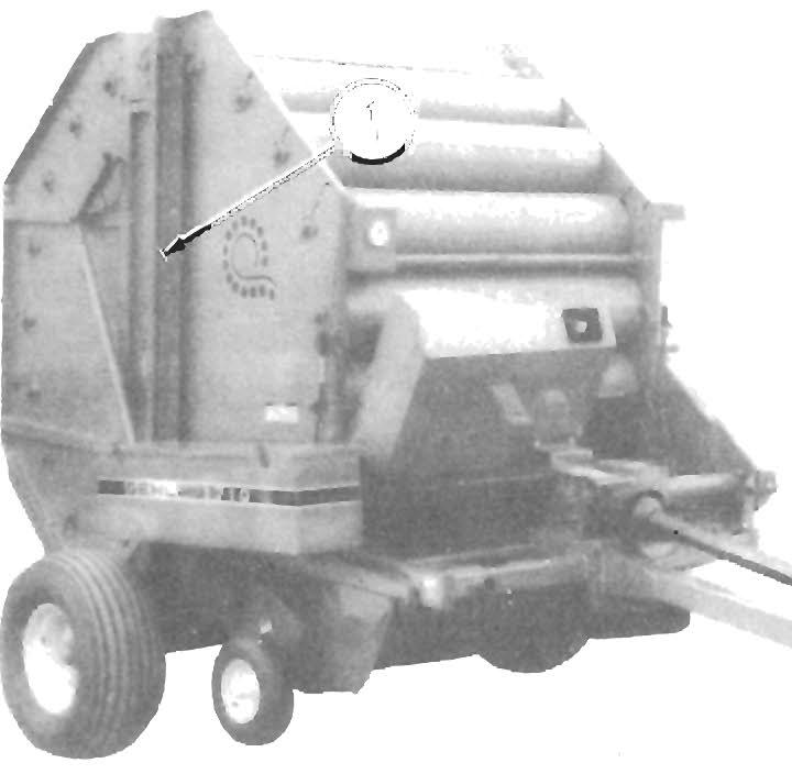
Holder Rods are provided on the Doors to hold them open while servicing or making adjustments inside. BE SURE to keep the Side Doors closed and latched when ever the Baler is in operation. Also located on the left side of the Baler are a hinged and Latched Shield (near the bottom front) to cover and protect the Pickup Drive and two bolt-on Shields (along the bottom) which are for service access during maintenance.
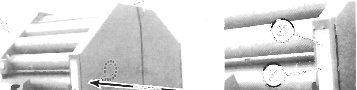
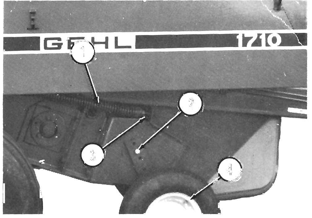
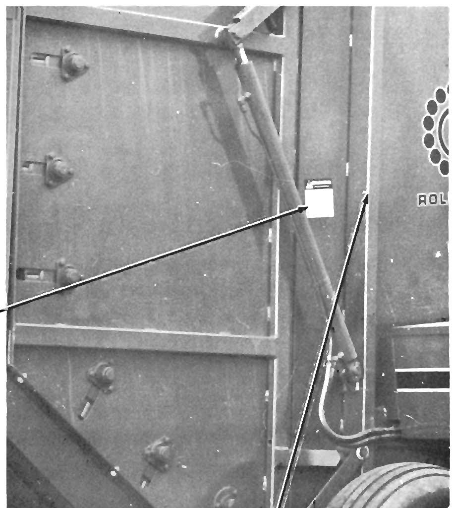
Rear Door Dust Panels (See Fig. 5-2) The Baler Rear Door is provided with Dust Panels, which also serve as Shields to protect the Rear Door Rollers. The hinged Upper Dust Panel is secured with two (2) Rubber hook-type Latches to provide for easier access to remove accumulated dust. The Lower Dust Panel is secured with six (6 each) Cap Screws, Nuts and Washers.
A CAUTI ON BEFORE proceeding to perform any work on the Baler and, BEFORE removing or opening any Shields, BE SURE to exercise the MAN· DATORY SAFETY SHUTDOWN PROCEDURE (page 8). Also, BE SURE to reinstall and/or close ALL Shields BEFORE operating the Baler.
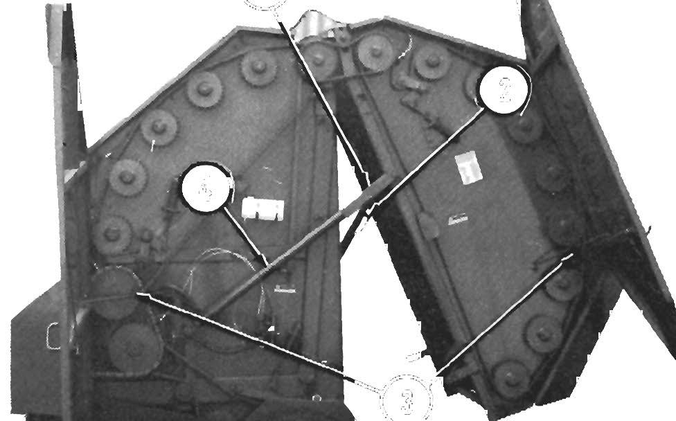
1 - Hinged Side Doors 2 - Hinged Upper Dust Panel 3 - Rubber Hook-type Latches 4 - Bolt-on Lower Dust Panel 5 - Bolt-on Lower Shield 6 - Bolt-on Pickup Drive Shield 7 - Hinged Pickup Drive Shield
Fig. 5-2
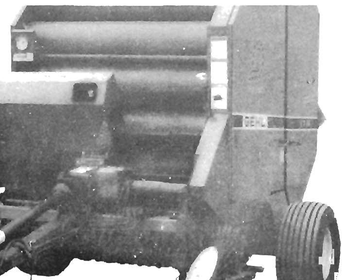
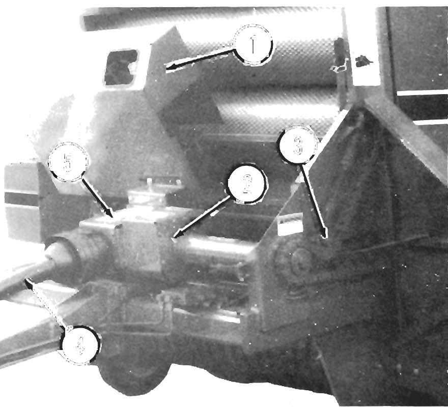
Left Side Shields & Doors (Figs. 5·2 & 5·3) Two large, hinged Side Doors, with Latch Handles, are provided on the left side of the Baler to cover and protect the Rollers and Rear Door Drive mechanisms.
16
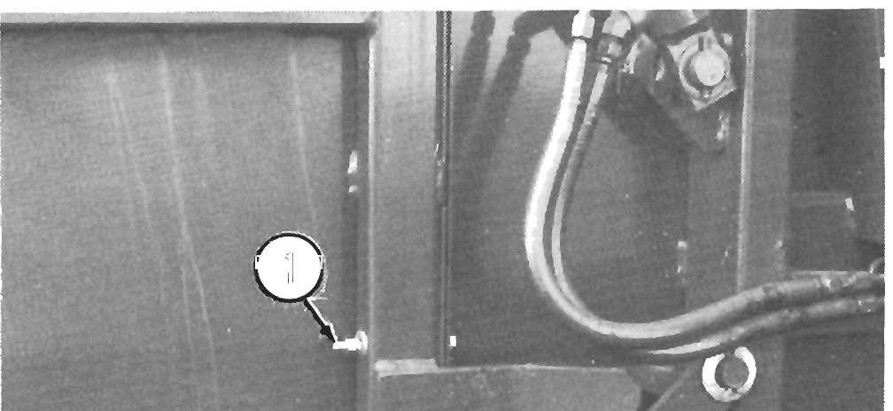
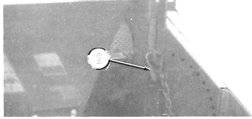
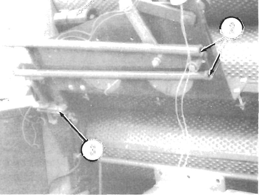
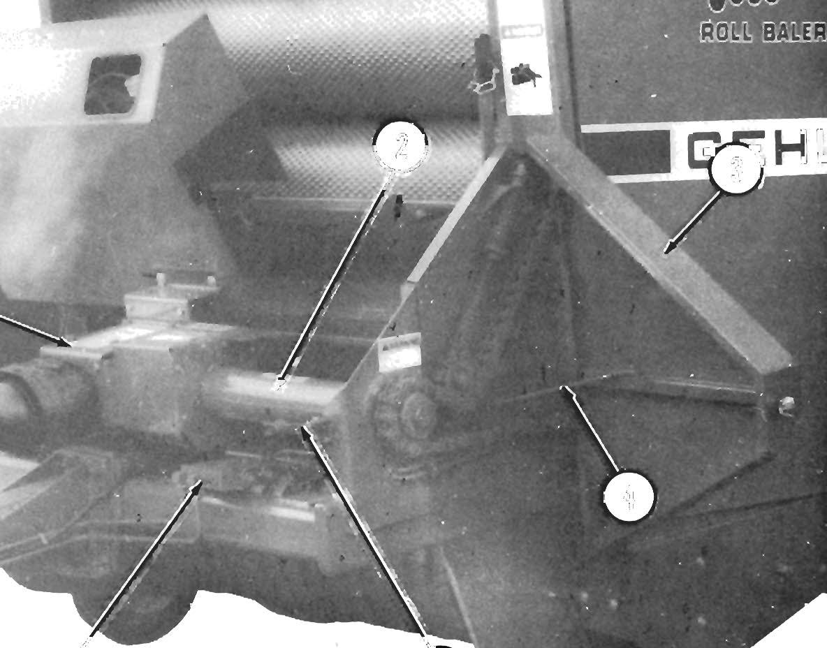
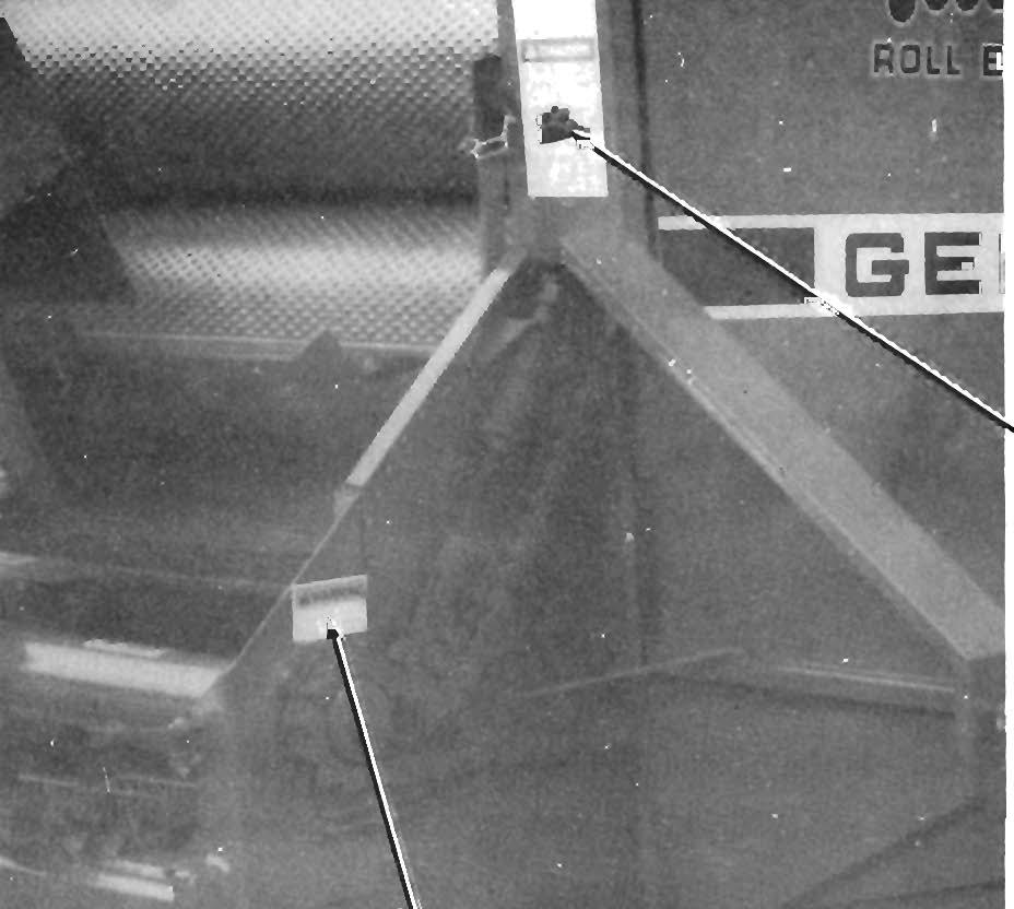
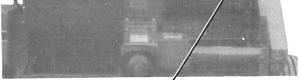
1 - Cylinder Lock In "Engaged" Position (1 each side) 2 - Cylinder Lock Latch Rod (1 each side) 3 • Side Door Holder Rods 4 - Rear Door Cylinder (1 each side)
Fig. 5-3