GETTING TO KNOW YOUR GRINDER CONTROL PANEL COMPONENT IDENTIFICATION FOR THE BG1500
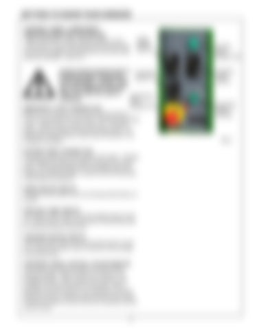
GRIND MOTOR SWITCH
Learn the function of each switch and knob on the control panel. As you read and learn about each knob you are encouraged to turn that knob on and view that particular operation. See FIG. 1.
ALWAYS WEAR PROPER SAFETY TRAVERSE EYEWEAR WHEN OPERATING SWITCH YOUR GRINDER. NEVER TURN ON YOUR GRINDER WITHOUT FIRST PUTTING ON SAFETY EMERGENCY EYEWEAR. STOP PUSHBUTTON
EMERGENCY STOP PUSHBUTTON Push in to cut all power to the control panel functions. This removes power from all motors, including the grinding motor, coolant pump, traverse motor, etc. To restore power, pull up on button and press the Start button. The large button design allows a quick stop of all power in an emergency situation. SYSTEM START PUSHBUTTON The green pushbutton is the system start switch. Pushing it will engage the magnetic starter and power the control panel. The magnetic starter will not engage unless the emergency stop pushbutton is pulled out and the grinding motor switch is turned off. GRIND MOTOR SWITCH The grind motor switch turns the Grinding Wheel Motor on and off. COOLANT PUMP SWITCH The coolant pump switch turns the coolant pump on and off. There is also a valve on the side of the grinding head to control the amount of the flow. TRAVERSE MOTOR SWITCH The travel motor switch turns the traverse motor on and off. It controls the side to side movement of the carriage and grinding head. TRAVERSE SPEED CONTROL POTENTIOMETER This control knob sets the speed of traverse for the grinding carriage. When turned on to minimum, the carriage will stop. When turned to the maximum, the carriage moves back and forth at full speed. When learning to use this machine, it is a good idea to set this speed at minimum, start the other functions, then slowly increase the speed to observe that your operation and set up are correct.
9
SYSTEM START PUSHBUTTON COOLANT PUMP SWITCH
TRAVERSE SPEED CONTROL
FIG. 1

