CAT FEEDER BREAKER FBL-10 LHD/UTILITY SERVICE MANUAL – PDF DOWNLOAD

Page 252

BI620123

Service Manual

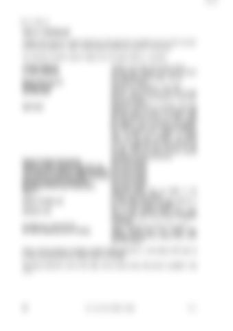
DISPLAY ASSEMBLIES Display LEDs signal the various functions of the electronic shutdown system to the operator or to service personnel. Light emitting diodes (LEDs) are used for this purpose. The electronic shutdown system display has 13 display LEDs on it as below. Hi Alarm Methane Lo Alarm Methane

methane level high, shuts down engine. warning that methane level has increased but is still safe, engine keeps running. Engine Oil Pressure shuts down engine. Charge Failure alternator not charging or circuit fault. Run Solenoid solenoid turned off, fault with one of the sensors, solenoid fault solenoid circuit fault, shuts down engine. Start Fault engine will start and run normally, but if the start light stays on, there is a problem with the start pressure switch or its cable. When this happens, the oil pressure and coolant flow timers on the control board are affected. The oil pressure and coolant circulation lights will still work normally (i.e. signal low/no oil pressure and low/no circulation) but the engine will not shutdown for ten minutes. The faulty switch or circuit should be repaired as soon as possible. Engine Coolant Temperature shuts down engine. Engine Coolant/Hydraulic Oil Level Low shuts down engine. Low Exhaust Conditioner Water Shutdown shuts down engine. Low Exhaust Conditioner Water Shutdown shuts down engine. Exhaust Outlet Gas Temperature shuts down engine. Pre-Exhaust Filter Gas Temperature shuts down engine. Spare 1 additional sensor may be added to the system, shuts down engine. Battery Voltage Low all lights flash (engine will keep going for a time, but system needs attention). Methane Fault one or both methane alarm lights flash engine shuts down but not due to presence of methane. Any Sensor or Cable Fault relevant light flashes, shuts down engine. All LEDS Flashing One on Steady battery charge level low, steady light indicates that there is a sensor fault, shuts down the engine. Every time the electronic shutdown system is first switched on, all the display LEDs light up for about five seconds thus checking their functionality. The single diagnostic light on the main control board shows that power is applied to the board.

244

FBL 10 LHD/Utility Serial No. 80042

Rev. 0


Turn static files into dynamic content formats.

Create a flipbook

Articles inside

Elevated Work Platform

2min
pages 335-338

Concrete Hopper

1min
page 339

15000 KG Side Shit Forks

1min
pages 321-322

5th Wheel Adaptor Materials Pod………………………………………………319

3min
pages 325-328

10000 KG Fixed Jib Crane

1min
pages 323-324

Spade Lip Ejector Blanket Straight Lip Ejector Blanket………………………………311 RAS Ejector Blanket………………………………………312

3min
pages 318-320

Safety Precautions

1min
page 317

General Description

1min
pages 315-316

Operator’s Horn

1min
page 312

Brake and Transmission Interlock System

1min
page 311

Air Receiver

4min
pages 305-307

Safe Start System

1min
page 310

Safety Precautions Air Compressor

1min
page 303

General Description

2min
pages 301-302

Starter Motor

1min
page 308

Articulation Joint

1min
page 296

Compartment Door Assembly

1min
page 292

Control Lever Maintenance

1min
page 271

Rapid Attach Back Plate (RAS) Assembly Rear Frame

1min
pages 288-289

Steering Wheel

1min
page 273

Emergency Intake Shut Off Valve

1min
pages 281-282

Park Brake Button

1min
page 269

Compartment Door

1min
page 267

Fault Guide

5min
pages 265-266

Testing Methane Sensor

2min
page 264

Display Assemblies

2min
pages 252-254

Checks and Calibration

1min
page 261

Electronic Shut down system

1min
pages 250-251

Alternator Drive Assembly Instruments and Controls

1min
page 249

Sensors and Locations

4min
pages 255-259

Methane Sensor Head

1min
page 260

Electrical System Troubleshooting

2min
pages 245-246

Engine Service Hour Meter

1min
page 244

Electric Lighting Components

2min
pages 241-243

Tilt and Lift Circuits

1min
page 233

Alternator Circuit and Cooling Fan

1min
pages 235-236

Attachment Controls Control Levers

1min
pages 229-230

Main Control Valve Bank

1min
pages 231-232

RAS Attach and PTO Circuits

1min
page 234

Brake Heads

1min
page 228

Brake Valve

5min
pages 224-227

Brake Accumulator

1min
page 223

Steering Control Valve Brake Circuit

1min
page 222

Steering/Brake Pump Pressure Filter Steering Circuit

2min
pages 219-220

Steering and Brake Hydraulic Manifold

3min
pages 215-218

General Description

2min
page 203

Steering Accumulator

1min
page 221

Checking and Cleaning Filler Neck Screen

1min
page 213

Auxiliary Hydraulic Pumps

1min
page 210

Safety Precautions

2min
pages 204-205

Safety Precautions

1min
page 196

Installation

1min
page 202

Removing and Installing the Front Drive Line

2min
page 198

Checking Wear of the Posi-Stop Brake Assemblies Drive Lines

1min
page 194

Cooled Brakes

2min
page 193

Checking/Filling the Axle Centre Oil Level Changing the Oil In Axle Centres, Wheel Ends, and Liquid

1min
pages 191-192

Checking/Filling the Planetary Wheel End Oil Level

1min
page 190

Service Data

2min
pages 186-188

Changing the Transmission Oil Filter Element

1min
page 182

Troubleshooting Guide

2min
pages 184-185

Changing the Transmission Oil

1min
page 183

Transmission and Torque Converter Checking/Filling the Transmission Oil

1min
page 181

Safety Precautions

1min
page 180

General Description

4min
pages 178-179

Cable Adjustment

1min
page 168

Removal and Installation of Drive Coupling Transmission/Torque Converter

1min
page 177

General Description

1min
page 156

Exhaust Outlet Flame Trap

1min
page 164

Exhaust Conditioner

4min
pages 160-163

Flushing a Contaminated Cooling System Exhaust System

1min
page 155

Checking/Filling and Flushing Coolant System

2min
page 154

Radiator

1min
pages 152-153

Fan Assembly

1min
page 150

General Description

1min
page 147

Emergency Intake Shutoff Valve

1min
page 143

Servicing Air Intake System Cooling System

1min
pages 145-146

Inlet Flame Trap/Flameproof Joints

1min
page 144

Air Cleaner/Indicator Assembly

2min
page 142

Flushing the Lubrication System Air Intake System

1min
page 140

Oil Filter

1min
page 138

250 Hours—3 Months Off Line Mechanical Inspection

9min
pages 55-66

Fuel System – Priming Lubrication System

1min
page 135

General Description

1min
page 136

50 Hours—Weekly Off Line Mechanical Inspection

9min
pages 45-54

500 Hours—6 Months Off Line Mechanical Inspection

9min
pages 67-78

Safety Precautions

1min
page 130

10 Hours—Daily Off Line Mechanical Inspection

8min
pages 35-44

Maintenance Schedules

1min
page 34

Diesel Fuel Relevant Information

2min
page 18

General Safety and Precaution General

3min
pages 30-32

Fuel Additives

1min
page 17

Specifications Lubrication and Fuel Specifications

4min
pages 14-15

Safety Labels and Instructions

1min
page 10

Hydraulic Isolation

2min
pages 24-25

Packing and Supporting the Machine

1min
page 33

Articulation Isolation

1min
page 27
Issuu converts static files into: digital portfolios, online yearbooks, online catalogs, digital photo albums and more. Sign up and create your flipbook.